Status of This Document
This section describes the status of this document at the time of its publication. Other documents may supersede this document. A list of current FIDO Alliance publications and the latest revision of this technical report can be found in the FIDO Alliance specifications index at https://fidoalliance.org/specifications/.
This document was published by the FIDO Alliance as a Review Draft.
This document is intended to become a FIDO Alliance Proposed Standard.
If you wish to make comments regarding this document, please Contact Us.
All comments are welcome.
This is a Review Draft Specification and is not intended to be a basis for any implementations as the Specification may change. Permission is hereby granted to use the Specification solely for the purpose of reviewing the Specification. No rights are granted to prepare derivative works of this Specification. Entities seeking permission to reproduce portions of this Specification for other uses must contact the FIDO Alliance to determine whether an appropriate license for such use is available.
Implementation of certain elements of this Specification may require licenses under third party intellectual property rights, including without limitation, patent rights. The FIDO Alliance, Inc. and its Members and any other contributors to the Specification are not, and shall not be held, responsible in any manner for identifying or failing to identify any or all such third party intellectual property rights.
THIS FIDO ALLIANCE SPECIFICATION IS PROVIDED “AS IS” AND WITHOUT ANY WARRANTY OF ANY KIND, INCLUDING, WITHOUT LIMITATION, ANY EXPRESS OR IMPLIED WARRANTY OF NON-INFRINGEMENT, MERCHANTABILITY OR FITNESS FOR A PARTICULAR PURPOSE.
1. Introduction
This document specifies the protocol interactions and message formats for the FIDO Device Onboard (FDO) protocols. FIDO Device Onboard is a device onboarding scheme from the FIDO Alliance, sometimes called "device provisioning".
Device onboarding is the process of installing secrets and configuration data into a device so that the device is able to connect and interact securely with an IoT platform. The IoT platform is used by the device owner to manage the device by: patching security vulnerabilities; installing or updating software; retrieving sensor data; by interacting with actuators; etc. FIDO Device Onboard is an automatic onboarding mechanism, meaning that it is invoked autonomously and performs only limited, specific, interactions with its environment to complete.
A unique feature of FIDO Device Onboard is the ability for the device owner to select the IoT platform at a late stage in the device life cycle. The secrets or configuration data may also be created or chosen at this late stage. This feature is called "late binding".
Various events may trigger device onboarding to take place, but the most common case is when a device is first "unboxed" and installed. The device connects to a prospective IOT platform over a communications medium, with the intent to establish mutual trust and enter an onboarding dialog.
Due to late binding, the device does not yet know the prospective IOT Platform to which it must connect. For this reason, the IOT Platform shares information about its network address with a "Rendezvous Server." The device connects to one or more Rendezvous Servers until it determines how to connect to the prospective IOT platform. Then it connects to the IOT platform directly.
The device is configured with instructions (RendezvousInfo) to query Rendezvous Servers. These instructions can
allow the device to query network-local Rendezvous Servers before Internet-based Rendezvous Servers.
In this way, the discovery of the IOT Platform can take place on a closed network.
FIDO Device Onboard is designed so that the device initiates connections to the Rendezvous Server and to the prospective IOT Platform, and not the reverse. This is common industry practice for devices connected over the Internet.
FIDO Device Onboard works by establishing the ownership of a device during manufacturing, then tracking the transfers of ownership of the device until it is finally provisioned and put into service. In this way, the device onboarding problem can be thought of as a device "transfer of ownership" or delegation problem. In a common situation for FIDO Device Onboard that uses the "untrusted installer" model, an initial set of credentials and configuration data is configured during manufacturing. Between when the device is manufactured and when it is first powered on and given access to the Internet, the device may transfer ownership multiple times. A structured digital document, called an Ownership Voucher, is used to transfer digital ownership credentials from owner to owner without the need to power on the device.
In onboarding, an installer person performs the physical installation of the IOT device. In the untrusted installer model, the device takes no guidance on how to onboard from an installer person who has powered on the device. The FIDO Device Onboard protocols are invoked when the device is first powered on. By protocol cooperation between the device, the Rendezvous server, and the new owner, the device and new owner are able to prove themselves to each other, sufficient to allow the new owner to establish new cryptographic control of the device. When this process is finished, the device is equipped credentials supplied by the new owner.
In the trusted installer model, the device is able to take advice and input from the installer person. Where this change in the trust relationship between the device and the installer person is appropriate, it can simplify onboarding.
Support for a trusted installer model is planned for a future release of FIDO Device Onboard.
The FIDO Device Onboard protocol does not limit or mandate the specific credentials supplied by the new owner to the device during onboarding. FIDO Device Onboard allows the manager to supply a variety of keys, secrets, or credentials and other associated data to the device so that it can be remotely controlled and enter service efficiently. The flexibility of the kind and quantity of credentials is an enabling feature for late binding of device to its IOT platform.
As an example, the device may be provisioned with: the Internet address and public key of its manager; a random number to be used as a shared secret; a key pair whose public key is in a certificate signed by a trusted party of its manager. Such credentials would permit an mTLS connection between device and manager, with additional functions controlled by a shared secret.
Once a device is under management, the FIDO Device Onboard credentials are updated to allow for future use in repurposing the device. Then FIDO Device Onboard enters a dormant state and the device enters normal IOT operations. Subsequent incremental update of the device may be performed by the manager, outside of FIDO Device Onboard. However, if the device is to be sold or re-provisioned, the manager may choose to clear the device of all local credentials and data, and re-enable FIDO Device Onboard.
We assume the device has access, when it is first powered on, to a network environment for installation, either the Internet, a sub-network of Internet (sometimes called an "intranet") or a closed network. The mechanism for device entry to the network is outside the scope of this document.
During manufacturing, a FIDO Device Onboard equipped device is ideally configured with:
-
A processor containing:
-
A Restricted Operating Environment (ROE), which is a combination of hardware and firmware that provides isolation of the necessary FIDO Device Onboard functions and applications on the device.
-
An FIDO Device Onboard application that runs in the processor’s ROE that maintains and operates on device credentials
-
A set of device ownership credentials, accessible only within the ROE:
-
Rendezvous information for determining the current owner of the device
-
Hash of a public key to form the base of a chain of signatures, referred to as the Ownership Voucher
-
Other credentials, please see § 3.4.1 Device Credential Persisted Type (non-normative) for more information.
-
FIDO Device Onboard may be deployed in other environments, perhaps with different expectations of security and tamper resistance. These include:
-
A microcontroller unit (MCU), perhaps with a hardware root of trust, where the entire system image is considered to be a single trusted object
-
An OS daemon process, with keys sealed by a Trusted Platform Module (TPM) or in the filesystem
The remainder of this document presumes the preferred environment, as described previously.
1.1. Transmitted Protocol Version
The FIDO Device Onboard protocol described in this document has protocol version: 1.0
Every message of the transmitted protocol for FIDO Device Onboard specifies a protocol version. This version indicates the compatibility of the protocol being transmitted and received. The actual number of the protocol version is a major version and a minor version, expressed in this document with a period character ('.') between them.
The protocol version is encoded into protocol messages differently; see section § 3.2 Base Types.
The specification version may be chosen for the convenience of the public. The protocol version changes for technical reasons, and may or may not change for a given change in specification. The protocol version and specification version may be different values, although a given specification must map to a given protocol version.
Owner and Rendezvous Server components MAY support multiple versions of the protocol, as the protocol evolves. This will allow newer and older devices to onboard successfully. The Device MAY support only a single protocol version; the Owner and Rendezvous Server can onboard the device if they have support for this version.
It is intended that the protocol major version be used for major changes to the protocol that are not expected to be backwards compatible within a single implementation, while the protocol minor version is intended for lesser changes that a single code base could implement as conditionals within the code. The actual implementation of support for one or more particular versions is entirely up to the implementation.
The receiving party of a message can use the protocol version to verify:
-
That the version is supported by the receiver
-
That the version is the same as with previous received messages in the same protocol transaction
-
Whether the receiver needs to invoke a backwards compatibility option. Since FIDO Device Onboard allows the device to choose any supported version of the protocol, this applies to the Owner or Rendezvous Server.
1.2. Correlation Attack Concerns
FIDO Device Onboard has a number of protocol features that make it hard for 3rd parties to track information about a device’s progress from manufacturing to ownership, to resale or decommissioning. This is a limited mechanism for cryptographic privacy where parties not involved in a transaction are limited in their view of it.
Since devices to be onboarded are newly manufactured or assumed to be reconditioned for transfer of ownership, it is unlikely that they contain Personally Identifiable Information (PII), so this cryptographic privacy is not related to a social privacy concern. Instead, the concern is that a device’s appearance on a network during automatic onboarding might be correlated to the device’s previous or future target service location, such that this correlation might enhance the knowledge of an attacker about the device’s system responsibilities and/or potential vulnerabilities.
Towards this concern, all keys exposed by protocol entities in FIDO Device Onboard can be limited to be used only in FIDO Device Onboard. The Transfer Ownership Protocol 2 (TO2) allows onboarding of additional device credentials, so that the "application keys" used during device operation are distinct from the keys used in FIDO Device Onboard.
The Intel® Enhanced Privacy ID (Intel® EPID [iso20008-1][iso20009-1]) can be used for attestation during onboarding. This attestation associates only a group identity with transfer of ownership, without allowing device correlation to the Rendezvous server or to anyone monitoring Internet traffic at the Rendezvous server. Intel® EPID may also be used to prove manufacturer and model number to a prospective owner without identifying device.
Attestation keys described in this specification, other than Intel® EPID, use key material that is unique to the device. This key material makes it possible to correlate the use of a device during subsequent invocations of FIDO Device Onboard. There are ways to avoid this correlation:
-
The device may only use FIDO Device Onboard once in its lifetime, and be decommissioned (i.e., destroyed) thereafter
-
The device may use FIDO Device Onboard only in a context, such as a closed network, where correlation of the device key provides no useful information to an attacker
Transfer Ownership protocol 2 (TO2), on successful completion, replaces all FIDO Device Onboard keys and identifiers in the device, except the attestation key mentioned above. This information may not be correlated with subsequent attempts to use FIDO Device Onboard information used in the future. When Intel® EPID is used as the attestation key, the key mechanism provides only group identification; if the groups sharing the same public key are large enough, it also becomes hard to identify individual devices based on their public key usage.
The FIDO Device Onboard protocols have been designed so that IP addresses can be allocated dynamically by the device owner to prevent correlation of device to IOT platform. This does not prevent a determined adversary from using IP addresses to trace this information, but can raise the bar against more casual attempts to trace devices from outside to inside an organization.
1.3. FIDO Device Onboard Terminologies
Refer to the FIDO Device Onboard Glossary document.
See also protocol entities definitions in: § 2.3 Protocol Entities
Specific entries that help in reading this document:
-
Device: The IoT or other device being onboarded
-
Device Credential: a set of credentials stored in the device at manufacture. See § 3.4.1 Device Credential Persisted Type (non-normative)
-
Owner (aka "Final Owner): The last owner in the chain of ownership through the supply chain. This is the entity which wishes to onboard the Device
-
Ownership Voucher: (§ 1.5.3 Ownership Vouchers) A credential, passed through the supply chain, that allows an Owner to verify the Device and gives the Device a mechanism to verify the Owner.
-
Owner Key: The Final Owner’s key pair, reflected as the last entry in the Ownership Voucher.
-
Rendezvous 'blob': a datum that gives addressing options for a device to contact a prospective Owner and perform the Transfer Ownership Protocol 2.
1.4. FIDO Device Onboard Transport Interfaces
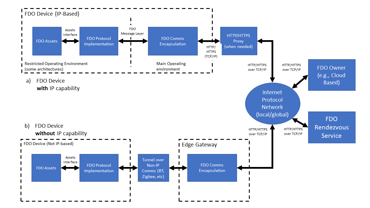
Figure 1 describes the way in which FIDO Device Onboard data is transported. FIDO Device Onboard protocols are defined in terms of an FIDO Device Onboard message layer (§ 2.1 Message Passing Protocol) and an encapsulation of these messages for transport to FIDO Device Onboard network entities (§ 4 Data Transmission).
FIDO Device Onboard Devices may be either natively IP-based or non-IP-based. In the case of FIDO Device Onboard Devices which are natively connected to an IP network, the FIDO Device Onboard Device is capable of connecting directly to the FIDO Device Onboard Owner or FIDO Device Onboard Rendezvous server.
The initial connection of the Device to the IP network is outside the scope of this document. FIDO Device Onboard is designed to allow an explicit or implicit HTTP proxy to operate as a network entry mechanism, when HTTP or HTTPS transport is used. The decision to use this or another mechanism is also out of scope for this document.
FIDO Device Onboard Devices which are not capable of IP protocols can still use FIDO Device Onboard by tunneling the FIDO Device Onboard message layer across a reliable non-IP connection. FIDO Device Onboard messages implement authentication, integrity, and confidentiality mechanisms, so any reliable transport is acceptable.
The FIDO Device Onboard message layer also permits FIDO Device Onboard to be implemented end-to-end in a co-processor, Trusted Execution Environment, or Restricted Operating Environment (ROE). However, security mechanisms must be provided to allow credentials provisioned by FIDO Device Onboard to be copied to where they are needed. For example, if FIDO Device Onboard is used to provision a symmetric secret into a co-processor, but the secret is used in the main processor, there needs to be a mechanism to preserve the confidentiality and integrity of the secret when it is transmitted between the co-processor and main-processor. This mechanism is outside the scope of this specification.
1.5. FIDO Device Onboard Base Profile (Normative)
This section defines a base profile that is normative for all compliant FIDO Device Onboard implementations. This profile constitutes base connectivity for FIDO Device Onboard components.
In FIDO Device Onboard, there is no protocol negotiation of optional features. The Device may choose any options and the burden of compatibility falls on the Owner and Rendezvous Server components.
This section references protocol entities. These are defined in: § 2.3 Protocol Entities
1.5.1. Protocols
FIDO Device Onboard entities SHALL support transport protocols as follows:
| Entity | Protocol | Requirement |
|---|---|---|
| Rendezvous Server | TO0 & TO1 | HTTP and HTTPS |
| Owner | TO0 & TO2 | HTTP and HTTPS |
| Device | TO1 & TO2 | Either HTTP or HTTPS |
1.5.2. Device Attestation
Regarding Device attestation, using Entity Attestation Token (EAT) cryptography (i.e., Device attestation), FIDO Device Onboard components SHALL support attestation and verification using cryptography:
-
ECDSA signatures, based on SECP256R1 or SECP384R1, encoded using COSEX509 or X.509
-
Intel® EPID signatures, based on StEPID10 and StEPID11
as follows:
| Entity | Protocol | Requirement |
|---|---|---|
| Rendezvous Server | TO1 | Verify any attestation, as above. |
| Owner | TO2 | Verify any attestation, as above. |
| Device | TO2 |
Generate at least one attestation signed with cryptography, above. Although it is legal for a device to support multiple cryptographic options for device attestation, we anticipate that the device manufacturer will pre-configure a single cryptographic attestation for purposes of FIDO Device Onboard. |
1.5.3. Ownership Vouchers
Regarding Ownership Vouchers generated, extended and verified, FIDO Device Onboard components SHALL be able to process Ownership Vouchers with cryptography:
-
Hash: SHA256 or SHA384
-
MAC: HMAC-SHA256 or HMAC-SHA384
-
Signature:
-
RSA public keys and signatures, encoded in X.509
-
ECDSA public keys and signatures, based on SECP256R1 or SECP384R1 encoded using X.509 or COSEX509
-
as follows:
| Entity | Protocol/Activity | Requirement |
|---|---|---|
| Owner | Receive Ownership Voucher from Supply Chain | Verify all combinations, as above |
| Rendezvous Server | TO0 | Verify all combinations, as above |
| Owner | TO2 | Verify all combinations, as above. |
| Device | TO1 & TO2 |
Verify at least one combination of cryptographic options (hash, MAC, signature), as above. Although it is legal for a device to support multiple cryptographic options for Ownership Voucher attestation, the manufacturer is expected to "seed" the Ownership Voucher with a single option that works for the host; subsequent entities must extend the Ownership Voucher using the same cryptographic options, so that the Device is only required to implement a single option. |
1.5.4. Session cryptography (TO2 protocol)
FIDO Device Onboard components SHALL be support the following session cryptography:
-
Key Exchange using ECDH128, ECDH256, DHKEXid14, DHKEXid15, ASYMKEX2048, ASYMKEX3072
-
Confidentiality & integrity:
-
authenticated encryption: AES-GCM or AES-CCM, as given by
AESType -
encrypt-then-mac: as given by
AESPlainTypewith HMAC-SHA256 or HMAC-SHA384.
-
Support shall be as follows:
| Entity | Protocol/Activity | Requirement |
|---|---|---|
| Owner | TO2 | Generate and verify any combination of the above |
| Device | TO2 | From above, generate and verify at least one key exchange and one "Confidentiality & integrity" selection. |
2. Protocol Description
FIDO Device Onboard protocols pass standard-format messages between cooperating entities, which are listed in subsequent sections. The messages are defined independent of any transport protocol, permitting FIDO Device Onboard to operate over multiple transport protocols with different properties, such as:
-
HTTP/HTTPS/CoAP (Current implementation of FIDO Device Onboard)
-
Constrained Application Protocol (CoAP) [RFC7252]
-
TCP or TCP/TLS streams
-
Non-Internet protocols, such as Bluetooth® specification or USB* specification
FIDO Device Onboard messages are formatted and encoded as described in subsequent sections
2.1. Message Passing Protocol
FIDO Device Onboard messages are defined in § 5 Detailed Protocol Description. A message is logically encapsulated by a protocol-dependent header containing the message type, protocol version, and other transmission-dependent characteristics, such as the message URL and message length in bytes. The message header is transmitted differently for different transport protocols. For example, the message header may be encoded into the HTTP header fields.
The message body is a CBOR [RFC7049] object, as described in the following sections.
2.2. FIDO Device Onboard Document Conventions
The ultimate goal of this document is to define a number of protocols, each of which is a specific flow of messages. The messages are defined by base and composite data types.
This document specifies these items using CDDL [RFC8610].
Many CDDL structures in this document refer to CDDL arrays. In the specification, it is easier to refer to the elements by their CDDL key or their CDDL type; the reader will infer the array index.
CDDL permits array entries to have a CDDL
key (e.g., [key_of_this_int: int]), where the CDDL key
(key_of_this_int) for an array entry exists only in the
specification. This mechanism is used for common types
within an array. Another mechanism used is to create a type instance and
use it only in one context (cipherSuiteName = tstr) and refer to the type.
In either case, individual fields are represented using a dot syntax, to indicate containment of one CDDL/CBOR construct inside another. This does not imply in specific containment (i.e., whether maps or arrays). Protocol messages also use the protocol name with a dotted syntax.
For example:
TO2.HelloDevice.kexSuiteName
refers to the 3rd element of the TO2.HelloDevice array, which has type "kexSuiteName".
Where COSE and EAT complex objects comprise an entire message, the payload entries are used as if they were part of the base message. So:
TO2.ProveOVHdr.OVPubKey
is a useful shorthand for:
TO2.ProveOVHdr.CoseSignature.payload.$SigningPayloads.TO2ProveOVHdrPayload.OVPubKey
Similarly, in this array:
to1dBlobPayload = [
    to1dRV:       RVTO2Addr, ;; choices to access TO2 protocol
    to1dTo0dHash: Hash       ;; Hash of to0d from same to0 message
]
the first element may be referenced as to1dRV or RVTO2Addr, and
the reader will infer the element in to1dBlobPayload[0].
Examples of actual messages are presented in pseudo-JSON. The reader will understand that this refers to CBOR, and convert appropriately. For example:
[ ['str1',3] ]
refers to a CBOR array with 1 element, containing a CBOR array with 2 elements, the first being a text string (tstr) and the second being an unsigned integer (uint).
Base types from the CDDL specification are heavily used, especially as
defined in [RFC8610], see the standard prelude in Appendix D. The
CBOR "hash" representation (e.g., #0), also defined in the CDDL specification, is
also used.
CDDL plug-and-socket is used to simplify reference to COSE and EAT
tokens. Rather than define the entire token for each message where it
is referenced, the token is defined with payload "plugs" (e.g., $COSEPayloads) that are filled in for each message, such as:
$COSEPayloads /= ( thisMessagePayload )So a message may be read as: "this message is a COSE object with the following payload." While this does not generate the tightest CDDL specification for each message type, we feel it is easier to understand.
2.3. Protocol Entities
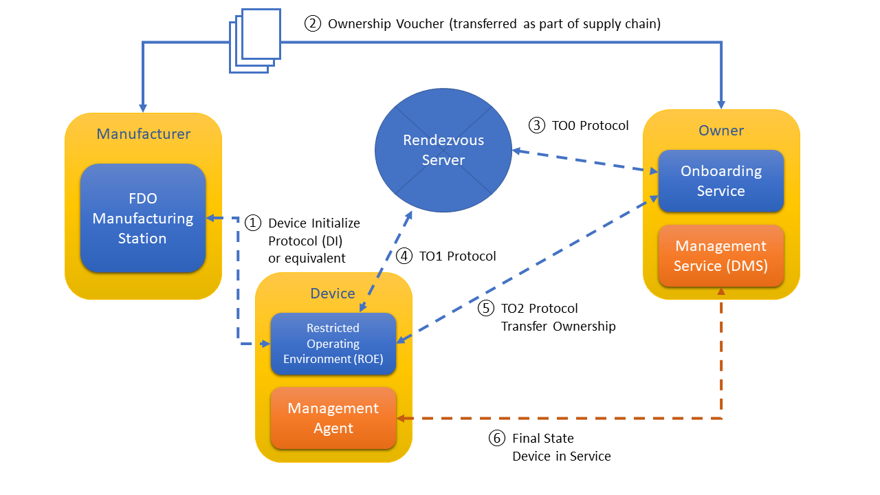
See Figure 2 for a diagram of FIDO Device Onboard Entities and their protocol interconnections.
-
Manufacturer (Mfg): Device manufacturer. A FIDO Device Onboard application runs in the factory, which implements the initial communications with the Device ROE, as part of the Device Initialize Protocol (DI) or appropriate substitute.
-
Device: The device being manufactured, later the device being provisioned. This device has hardware and software configured on it, including a Device ROE and a Device to Manager Agent. In the following documentation, a FIDO Device Onboard enabled Device is capitalized, to distinguish it from reference to the generic meaning of "device".
-
Device ROE: A Restricted Operating Environment within the Device. In some Devices, this is a co-processor or a special processor mode that enables a small kernel of code to run, with credentials to prove its authenticity.
-
Device ROE App: This is the application that is installed in the ROE of the device to provide the FIDO Device Onboard capabilities on the device. When we informally refer to the Device ROE as an endpoint to a protocol, we always mean the Device ROE App.
-
Device to Manager Agent: Software that runs on the device in normal operation that connects the device to its manager across the network. This entity’s function is specific to the Manager, and outside the scope of this document, except for its first connection to the Manager. Our intention is that the Device to Manager Agent matches as closely as possible the existing agents that connect devices to remote network or cloud managers.
-
Owner: This is an entity that is able to prove ownership to the Device using an Ownership Voucher and a private key for the last entry of the Ownership Voucher (the “Owner Key”). Various members of the supply chain may have bought and sold the device while it was still “boxed,” acting as owners, but without powering on the device. The final owner in the chain uses the Owner Onboarding Service to provision the device, and then controls it across a network using a Manager.
-
Manager: The entity that manages devices across a network. This can range from an application on a user’s computer, phone or tablet, to an enterprise server, to a cloud service spanning multiple geographic regions. The Manager interacts with the device using the Device to Manager Agent. Commonly, the Manager is an existing management system or cloud management service that is provisioned using FIDO Device Onboard, so that it operates the same as if it were manually provisioned.
In some cases, the owner elects to subscribe to a cloud service and proxy his ownership, so that the Manager controls the ownership credentials of the owner.
-
Owner Onboarding Service: This is an entity constructed to perform FIDO Device Onboard protocols on behalf of the Owner. The Owner Onboarding Service is an application that executes on some platform already controlled by the Owner. After the protocols are completed, the Owner Onboarding Service transfers control of the device to the Owner’s Manager, and never interacts with the device again. In FIDO Device Onboard, the Owner Onboarding Service is a component of the Manager, rather than a separate network service.
-
Rendezvous Server: A network server or service (e.g., on the Internet) that acts as a rendezvous point between a newly powered on Device and the Owner Onboarding Service. It is expected that Internet versions of the Rendezvous Server will comprise multiple actual servers and service points; the reader will understand that Rendezvous Server in this document applies to the aggregate service.
-
Management Service: The entity that uses the Owner Onboarding Service to take ownership of the Device, so that it can manage the device remotely using its own management techniques (protocols, etc.). During FIDO Device Onboard operation, the Management Service interacts with the Management Agent via the ServiceInfo (Section 5.2.5) key-value pairs.
A common industry term for "Management Service" is "Device Management Service" (DMS). Since Device is used in a special manner in this document, we shorten the term.
-
Management Agent: The entity that uses the FIDO Device Onboard Device software to allow the device ownership to be transferred using FIDO Device Onboard protocols. During FIDO Device Onboard operation, the Management Agent interacts with the Management Service via the ServiceInfo key-value pairs.
2.3.1. Entity Credentials
Each of the entities above identifies itself in FIDO Device Onboard protocols using cryptographic credentials. These are:
-
Device Attestation Key : FIDO Device Onboard uses cryptographic device attestation based on a signed Entity Attestation Token ([EAT]). The protocol can support many cryptographic mechanisms for device attestation but this spec supports two basic capabilities: Intel® EPID and ECDSA. For each of the methods, there is a private key that is provisioned into the device, such as when the CPU or board is manufactured, for establishing the trust for a Restricted Operating Environment (ROE) that runs on the device. When signed by the device attestation key, this provides evidence of the code being executed in the ROE.
-
Ownership Credential Key Pair: This is a key pair that serves temporarily to identify the current owner of the device. When the device is manufactured, the manufacturer uses a key pair to put in an initial ownership credential. Later, the protocols conspire specifically to replace this credential with a new ownership credential, effecting ownership transfer.
-
The Device Credential does not identify the owner in general, it identifies the owner for the purposes of ownership transfer. The device credential from the manufacturer, stored in the device, must match the credential at one side of the ownership voucher. That is all. It is not intended that this key pair permanently identify the manufacturer or any of the parties in the ownership voucher. On the contrary, we expect that the manufacturer may use different keys over time and the owners will also use different keys over time, specifically to obscure their identity in the FIDO Device Onboard protocols and increase of the robustness of FIDO Device Onboard.
2.3.2. Management Agent/Service interactions using ServiceInfo
In the Transfer Ownership Protocol 2 (TO2), after mutual trust is proven, and a secure channel is established, key-value pairs are exchanged. This is a mechanism for interaction between the Management Agent and Management Service using the TO2 protocol as a secure transport. The amount of information transferred using this mechanism is not specifically constrained by the TO2 protocol, but some structure is imposed in the definition of ServiceInfo (Section 5.2.5). The intent is to allow the Management Service to provision sufficient keys, data and executables to the Management Agent so that they are enabled to interact securely for the life of the device.
For example, a Management Agent may send a Public Key Cryptography Standards (PKCS#10) Certificate Signing Request (CSR) to the Management Service in a Device ServiceInfo key-value pair, which can use a certificate authority (CA) to provision a X.509 certificate, trusted by itself, and send that certificate back to the Management Agent in PKCS#7 format, all using an Owner ServiceInfo key-value pairs.
The flows of ServiceInfo information between the Owner and the Management Service, and between the Device and the Management Agent, are outside the scope of this document.
ServiceInfo provides a key-value pair mechanism. The namespace of keys is divided into module-specific spaces and key attributes allow for downloading of data files or executable code (e.g., installation scripts) using the trust provided by FIDO Device Onboard.
2.4. Protocol Entity Interactions
The following diagram shows the interaction between the protocol entities in the FIDO Device Onboard Protocols:
The following sections define these protocols.
It is expected the “final state” protocol (bottom arrow in the diagram) may be a pre-existing protocol between a manager agent and manager service that exist independently of FIDO Device Onboard. FIDO Device Onboard serves to provide credentials rapidly and securely so that the pre-existing software is able to take over and operate as if it were manually configured. FIDO Device Onboard is not used further by the device or owner unless the owner wishes to re-provision the device, such as to effect another ownership transfer.
Some of the interactions between entities are not defined in the protocols:
-
The manufacturer creates an Ownership Voucher based on the credentials in the Device Initialize Protocol (DI). The Ownership Voucher is a digital document that provides the Owner with the credentials to take ownership of the Device. It is extended with each owner while the device is offline (i.e., boxed or shipped) between Manufacturer and Owner. The Ownership Voucher is defined in [§ 1.5.3 Ownership Vouchers]. This specification does not indicate how the Ownership Voucher is transported from the Manufacturer to the Owner Onboarding Service, where it is used in the FIDO Device Onboard protocols.
-
The interaction between the Device ROE App and the Device to Manager Agent is system dependent.
-
The interaction between the Owner’s Manager Service and the Owner Onboarding Service is dependent on the implementation of these two components.
In addition, the Device Initialize Protocol § 5.2 Device Initialize Protocol (DI) is non-normative.
2.5. Protocols
The following protocols are defined as part of FIDO Device Onboard. Each protocol is identified with an abbreviation, suitable to use as a programming prefix. The abbreviations are also used in this discussion.
Table ‑. FIDO Device Onboard Protocols
| Protocol Name | Abbr. | Function |
|---|---|---|
| Device Initialize Protocol (DI) | DI | Insertion of FIDO Device Onboard credentials into device during the manufacturing process. |
| Transfer Ownership Protocol 0 (TO0) | TO0 | FIDO Device Onboard Owner identifies itself to Rendezvous Server. Establishes the mapping of GUID to the Owner IP address. |
| Transfer Ownership Protocol 1 (TO1) | TO1 | Device identifies itself to the Rendezvous Server. Obtains mapping to connect to the Owner’s IP address. |
| Transfer Ownership Protocol 2 (TO2) | TO2 | Device contacts Owner. Establishes trust and then performs Ownership Transfer. |
The following figure shows a graphical overview of these protocols. Graphical representations of each protocol are presented with the protocol details.
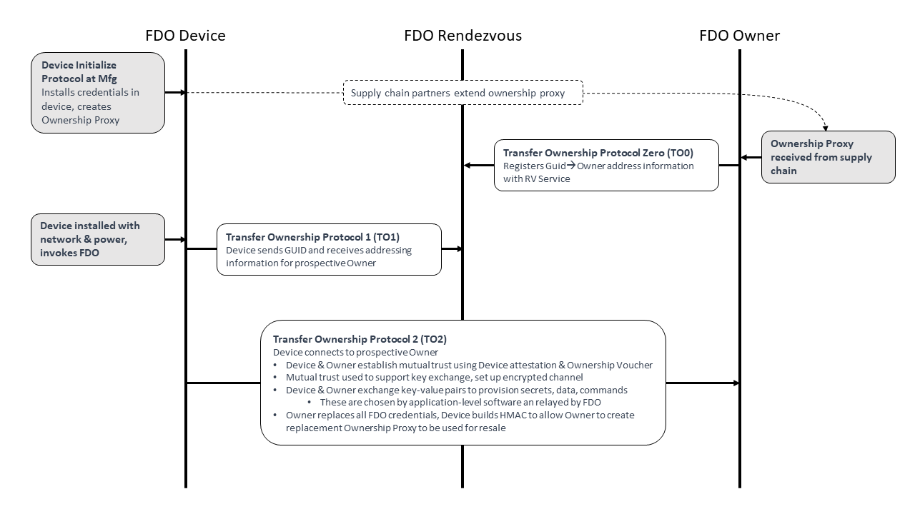
2.5.1. Device Initialize Protocol (DI)
The non-normative Device Initialize Protocol (DI) provides an example of a protocol that runs within the factory when a new device is completed. The protocol’s function is to embed the ownership and manufacturing credentials into the newly created device’s ROE. This prepares the device and establishes the first in a chain for creating an Ownership Voucher with which to transfer ownership of the device.
The Device Initialize Protocol assumes that the protocol will be run in a safe environment. The trust model is Trust on First Use (TOFU). When possible, the DI Protocol should use write-once memory to ensure the Device is not erased or reprogrammed after factory use. When no such hardware is available, it might be possible to reprogram the device, so as to create alternate FIDO Device Onboard credentials.
The Device Initialize Protocol starts with:
-
The physical device and the FIDO Device Onboard Manufacturing Component attached to a local network within the factory.
-
The FIDO Device Onboard Manufacturing Component has access to:
-
A key pair for device ownership, which will be used to create device credentials in the device and the Ownership Voucher. This key pair does not specifically identify the manufacturer (e.g., it is not in a certificate) and may be changed from time to time, so long as the Device Credential refers to the same key pair as the Ownership Voucher for that device.
-
Device description string (tstr), configured by the manufacturer.
-
Device ROE running the FIDO Device Onboard application. In one implementation, the Device PXE-boots into this application.
The Device Initialize Protocol ends with:
-
The FIDO Device Onboard Manufacturing Component has information and credentials to create an Ownership Voucher for the device or has the Ownership Voucher itself.
-
The Device has ownership and manufacturer credentials stored in its ROE. The Device should arrange to protect these credentials. Ideally:
-
Only the Device ROE software should be able to access these credentials.
-
The credentials are protected against modification by non-FIDO Device Onboard programs.
-
Any modification of the credentials by non-FIDO Device Onboard programs (despite measures above) is detectable.
-
-
The Device is ready to be powered off and boxed for shipment. No further network attachment is necessary.
-
The Device has a GUID that can be used to identify it to its new owner. This GUID is also known to the FIDO Device Onboard Manufacturing Component, and is in the Ownership Voucher. The GUID is not a secret. Specifically, the GUID is intended to be visible to the Owner when the device shipped in a box, perhaps being on the box itself with a bar code, perhaps being on the bill of lading. The GUID is used for one FIDO Device Onboard transfer of ownership only; after Transfer Ownership Protocol 2, the GUID is replaced, and the Device has no memory of the original GUID.
2.5.2. Transfer Ownership Protocol 0 (TO0)
Transfer Ownership Protocol 0 (TO0) serves to connect the Owner Onboarding Service with the Rendezvous Server. In this protocol, the Owner Onboarding Service indicates its intention and proves it is capable of taking control of a specific Device, based on the Device’s current GUID.
Transfer Ownership Protocol 0 starts with:
-
A presumed Device that has undergone the Device Initialize Protocol (DI) and thus has credentials in its ROE (DeviceCredential) identifying the Manufacturer public key that is in the Ownership Voucher. The Device is not a party to this protocol, and may be powered off, in a box, or in transit when the protocol is run.
-
The Owner Onboarding Service has access to the following:
-
An Ownership Voucher, whose last Public key belongs to the Owner, and the GUID of the device, which is also authorized by the Ownership Voucher.
-
The private key that is associated with the Owner’s public key in the Ownership Voucher.
-
An IP address from which to operate. This IP address need bear no relationship to the service addresses that are used by the Owner. The Owner may take steps to hide its address, such as allocating it dynamically (e.g., using DHCP) or using an IPv6 privacy address. The motivation for hiding this IP address is to maintain the privacy of the Owner from the Rendezvous Server or from anyone monitoring network traffic in the vicinity of the Rendezvous Server. This can never be done for sure; we think of it as raising the bar on an attacker.
-
-
The Rendezvous Server has some way to trust at least one key in the Ownership Voucher. For example, the Manufacturer has selected the Rendezvous Server, then the Rendezvous Server might be aware of the Manufacturer’s public key used in the Ownership Voucher.
Transfer Ownership Protocol 0 ends with:
-
The Rendezvous Server has an entry in a table that associates, for a specified interval of time, the Device GUID with the Owner Onboarding Service’s rendezvous 'blob.' The blob contains an array of {DNS name, IP address, port, protocol}.
-
The Owner Onboarding Service is waiting for a connection from the Device ROE at this DNS name and/or IP address for this same amount of time.
If the Device ROE appears within the set time interval, it can complete Transfer Ownership Protocol 1 (TO1). Otherwise, the Rendezvous Server forgets the relationship between GUID and Rendezvous 'blob.' A subsequent TO1 from the Device ROE will return an error, and the Device will not be able to onboard. The Owner Onboarding Service can extend the time interval by running Transfer Ownership Protocol 0 again. It may do so from a different IP address.
In the case of a Device being connected to a cloud service, the Owner Onboarding Service typically would repeatedly perform the TO0 Protocol until all devices known to it successfully complete the TO0 Protocol. In the case of a Device being connected using an application program implementation of the Owner Onboarding Service, the Owner might arrange to turn on the Owner Onboarding Service shortly before turning on the device, to expedite the protocol.
The Rendezvous Server is only trusted to faithfully remember the GUID to Owner blob mapping. The other checks performed protect the server from DoS attacks, but are not intended to imply a greater trust in the server. In particular, the Rendezvous Server is not trusted to authorize device transfer of ownership. Furthermore, the Rendezvous Server never directly learns the result of the device transfer of ownership.
2.5.3. Transfer Ownership Protocol 1 (TO1)
Transfer Ownership Protocol 1 (TO1) is an interaction between the Device ROE and the Rendezvous Server that points the Device ROE at its intended Owner Onboarding Service, which has recently completed Transfer Ownership Protocol 0. The TO1 Protocol is the mirror image of the TO0 Protocol, on the Device side.
The TO1 Protocol starts with:
-
A Device that has undergone the Device Initialize Protocol (DI) and thus has credentials (DeviceCredential) in its ROE identifying the particular Manufacturer Public Key that is in the Ownership Voucher. The Device is ready to power on.
-
An Owner Onboarding Service and Rendezvous Server that have successfully completed Transfer Ownership Protocol 0:
-
The Rendezvous Server has a relationship between the GUID stored in the device ROE and a rendezvous 'blob', as described above.
-
The Owner Onboarding Service is waiting for a connection from the Device ROE on the network addresses referenced in the rendezvous 'blob.'
If these conditions are not met, the Device will fail to complete the TO1 Protocol, and it will repeatedly try to complete the protocol with an interval of time between tries. The interval of time should be chosen with a random component to try to avoid congestion at the Rendezvous Server.
After the TO1 Protocol completes successfully:
-
The Device has rendezvous information sufficient to contact the Owner Onboarding Service directly.
-
The Owner Onboarding Service is waiting for a connection from the Device ROE on the network addresses referenced in the rendezvous 'blob.' I.e., it is still waiting, since it does not participate in the TO1 Protocol.
2.5.4. Transfer Ownership Protocol 2 (TO2)
Transfer Ownership Protocol 2 (TO2) is an interaction between the Device ROE and the Owner Onboarding Service where the transfer of ownership to the new Owner actually happens.
Before the TO2 Protocol begins:
-
The Owner has received the Ownership Voucher, and run Transfer Ownership Protocol 0 to register its rendezvous 'blob' against the Device GUID. It is waiting for a connection from the Device ROE on the network addresses referenced in this 'blob.'
-
The Device has undergone the Device Initialize Protocol (DI) and thus has credentials (DeviceCredential) in its ROE identifying the particular Manufacturer’s Public Key that is (hashed) in the Ownership Voucher.
-
The Device has completed Transfer Ownership Protocol 1 (TO1), and thus has the rendezvous 'blob', containing the network address information needed to contact the Owner Onboarding Service directly.
After the TO2 Protocol completes successfully:
-
The Owner Onboarding Service has replaced all the device credentials with its own, except for the Device’ attestation key. The Device ROE has allocated a new secret and given the Owner a HMAC to use in a new Ownership Voucher, which can be used for resale. See § 6 Resale Protocol.
-
The Owner Onboarding Service has transferred new credentials to the Device ROE in the form of key-value pairs. These credentials include enough information for the Device ROE to invoke the correct Device to Manager Agent and allow it to connect to the Owner’s Manager service. The set of parameters is given in the following messages, although the OwnerServiceInfo is an extensible mechanism. See § 3.8 ServiceInfo and Management Service – Agent Interactions.
-
TO2.SetupDevice (§ 5.5.7 TO2.SetupDevice, Type 65)
-
TO2.OwnerServiceInfo (§ 5.5.11 TO2.OwnerServiceInfo, Type 69)
-
-
The Owner Onboarding Service has transferred these credentials to the Owner’s Manager, which is now ready to receive a connection from the Device.
-
The Device ROE has received these credentials, and has invoked the Device to Manager Agent and given it access to these credentials.
-
The Device to Manager Agent has received these credentials is ready to connect to the Owner’s Manager.
In a given Device, there may be a distinction between: the Device ROE and the Device to Manager Agent; and between the Owner Onboarding Service and the Owner’s Manager:
-
The Device ROE performs the FIDO Device Onboard protocols and manipulates and stores FIDO Device Onboard credentials. The Device ROE is likely to store other credentials and perform other services (e.g., cryptographic services) for the device.
-
The Device itself runs its basic functions. Amongst these is the Device to Manager Agent, a service process that connects it to its remote Manager. This software is often called an “agent”, or “client.” We intend that this software can be a pre-existing agent for the Manager service chosen by the Owner, which may also operate on devices that do not use FIDO Device Onboard.
-
The Owner Onboarding Service is a body of software that is dedicated specifically to run the FIDO Device Onboard Protocol on behalf of the Manager. For example, this code might have its own IP addresses, so that the eventual Manager IP addresses (which may be well known) are hidden from prying eyes.
-
The Owner Manager is an Internet-resident service that provides management services for the Owner on an ongoing basis. FIDO Device Onboard is designed to work with pre-existing Manager services.
After Transfer Ownership Protocol 2, the FIDO Device Onboard specific software is no longer needed until and unless a new ownership transfer is intended, such as when the device is re-sold or if trust needs to be established anew. FIDO Device Onboard client software adjusts itself so that it does not attempt any new protocols after the TO2 Protocol. Implementation-specific configuration can be used to re-enable ownership transfer (e.g., a CLI command).
2.6. Routing Requirements
In an IP-based network, the Device must be able to route to the Rendezvous Server and the prospective Owner returned by the Rendezvous Server. A "closed" IP network with no path to the Internet can support FIDO Device Onboard if:
-
The Rendezvous Server has a network attachment within the closed network
-
The prospective Owner referenced by the returned RVInfo has a network attachment within the closed network
-
The Device can access a bidirectional route to to the IP address at the above attachments
For example, if the closed network uses addresses 192.168.0.0/16, then the Rendezvous Server and prospective Owner returned by the RVInfo and the Device itself must all have IP addresses within 192.168.0.0/16, and a route must exist between the Device that the other two.
2.7. The Ownership Voucher
The Ownership Voucher is a structured digital document that links the Manufacturer with the Owner. It is formed as a chain of signed public keys, each signature of a public key authorizing the possessor of the corresponding private key to take ownership of the Device or pass ownership through another link in the chain.
The following diagram illustrates an Ownership Voucher with 3 entries. In the first entry, Manufacturer A, signs the public key of Distributor B. In the second entry, Distributor B signs the public key of Retailer C. In the third entry, Retailer C signs the public key of Owner D.
The entries also contain a description of the GUID or GUIDs to which they apply, and a description of the make and model of the device.
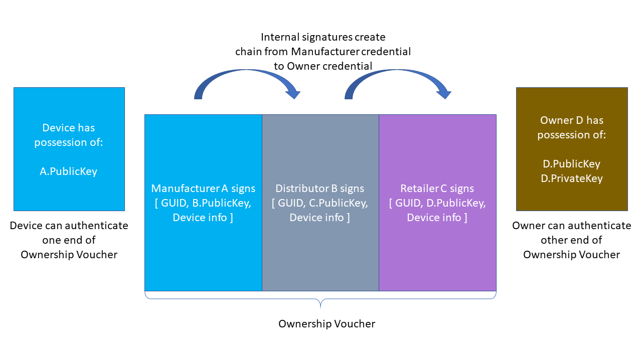
The signatures in the Ownership Voucher create a chain of trust from the manufacturer to the Owner. The Device is pre-provisioned (e.g., in the Device Initialize Protocol (DI)) with a crypto-hash of A.PublicKey, which it can verify against A.PublicKey in the Ownership Voucher header transmitted in the TO2 protocol. The owner can prove his connection with the Ownership Voucher (and thus his right to take ownership of the Device) by proving its ownership of D.PrivateKey. It can do this by signing a nonce, and the signature may be verified using D.PublicKey from the Ownership Voucher.
The last entry in the Ownership Voucher belongs to the current owner. The public key signed in that entry is the owner’s public key, signed by the previous owner. We call this public key the “Owner Key.”
In the TO2 Protocol, the Owner proves his ownership to the device using a signature (as above) and an Ownership Voucher that is rooted in A.PublicKey. The device verifies that the hash of A.PublicKey stored in its ROE matches A.PublicKey in the Ownership Voucher, then verifies the signatures of the Ownership Voucher in sequence, until it comes to D.PublicKey. The Owner provides the Device separate proof of D.PublicKey (the “owner key”), completing the chain of trust. The only private key needed to verify the Owner’s assertion of ownership is the key of the Owner itself. The public keys in the Ownership Voucher (and the public key hash in the Device) are sufficient to verify the chain of signatures.
The public keys in the Ownership Voucher are just public keys. They do not include other ownership info, such as the name of the entity that owns the public key, what other keys they might own, where they are, etc.
The Ownership Voucher is maintained only for the purposes of connecting a particular device with its particular first owner. The entities involved can switch the key pairs they use to sign the Ownership Voucher from time to time, make it more difficult for potential attackers to use the Ownership Voucher as a means to map out the flow of devices from factory to implementation.
Conversely, it is conceivable that a private data structure might contain supply chain identities, allowing the Ownership Voucher to specifically map the identities who signed it. The use of the Ownership Voucher for other than device onboarding is outside the scope of this specification.
| Note |
|---|
|
The Ownership Voucher signing operation need not be the same as the device attestation operation. For example, a device can use RSA or ECDSA for Ownership Voucher signing independent of whether it uses Intel® EPID or ECDSA for device attestation. However, the ownership voucher signing and key encoding must be consistent across all entries in the ownership voucher. This is required to ensure that the Device is able to process each entry. |
The Ownership Voucher is distinct from the Voucher Artifact described in [RFC8366], although both are structured documents that convey trust. The Ownership Voucher here conveys trust through the supply chain from the manufacturer, being the original 'owner' of the Device, to the ultimate Owner who will use the Device in a production setting. The Voucher Artifact is a dynamically generated object which provides an endorsement of the Device from a trusted authority (the "MASA").
3. Protocol Encoding and Primitives
FIDO Device Onboard defines base types, composite types (based on the base types), and protocol messages based on the composite types. Persisted Items indicate data structures that need to be persisted on storage and/or transmitted between FIDO Device Onboard entities outside the protocol. Some persisted items are non-normative. These are defined to make it easier for implementors to understand the data storage requirements for a given task.
CDDL
start /= (
    BaseTypes, CompositeTypes,
    DataStructures
    ProtocolMsg
)

DataStructures /= (
    DeviceCredential,  ;; in device
    OwnershipVoucher   ;; outside device
)

ProtocolMsg /= (
    ErrorMessage,
    DIProtocolMessages, TO0ProtocolMessages,
    TO1ProtocolMessages, TO2ProtocolMessages
)
3.1. CBOR Message Encoding
FIDO Device Onboard uses CBOR message encoding [RFC7049]. CBOR canonical form is not required. Generating FIDO Device Onboard messages in canonical form is permitted.
Implementations MUST NOT use CBOR indefinite length. The intent of this restriction is to limit memory usage on a constrained Device.
FIDO Device Onboard does not constrain the use of CBOR data types in COSE or EAT data structures, or in ServiceInfo values, except to exclude indefinite length.
When transmitting frames over a stream in FIDO Device Onboard, the initial length field’s size is constrained by the FIDO Device Onboard protocol. This intended to make it easier for low-level I/O drivers to read entire messages. See section § 4.2 Transmission of Messages over a Stream Protocol.
3.2. Base Types
CDDL
BaseTypes /= (
    ;; BaseTypes pulled in from CDDL specification
    int, uint,
    bool,
    tstr,
    bstr,

    ;; BaseTypes unique to this specification
    uint8, uint16, uint32,
    msgarray,
    uint16bits
)

;; Defined in CDDL spec and standard prelude
;; This summary is non-normative
;;int    = #0 / #1
;;uint   = #0
;;bool   = #7.20 / #7.21
;;tstr   = #3
;;bstr   = #2

;; Normative specification of specific types used below.
;;
;; Message array, must be encoded as a single byte, see below.
msgarray=#4

;; uint with no more than 16 bits magnitude.
;; We require 1, 2, or 3 byte encoding, although the following CDDL
;; expression permits a longer encoding (see text).
uint16bits = #0 .size 2

;; Type names used in the specification
protver = uint16bits
msglen = uint16bits
msgtype = uint16bits
The following types are imported, unchanged, from the CDDL specification [RFC8610], section 3.3:
-
int
-
uint
-
bool
-
tstr
-
bstr
Most FIDO Device Onboard integers are subsets of the uint type. To aid the protocol implementation, the requirements for storage are made more explicit, by indicating the storage size:
-
uint8 for 8 bits,
-
uint16 for 16 bits
-
uint32 for 32 bits
The encoding for transmission
MAY be any legal CBOR major type 0 (uint) encoding, so long as the storage
requirement for storing the value is not exceeded (i.e., a 9-byte
encoding for uint 255 still is considered a valid uint8). Owner
and Rendezvous Server implementations MUST check that particular transmitted values are in the range
for the type indicated, and Device implementations
SHOULD so check.
The following types are used for a fixed length stream header and MUST be encoded in a specific manner:
The msgarray type MUST be encoded as a single byte. This array
(major type 4) is
always 5 entries long, so the encoding is exactly: (4<<5)+5 = 0x85.
The uint16bits type MUST be encoded in 1, 2, or 3 bytes. This is
different from the uint16 type, which may have any uint encoding, but whose value must fit in 16 bits.
The protver type is used to transmit the version of the protocols in
this specification. Its value is always the same for a given protocol run:
protver_value = protocol_major_version * 100 + protocol_minor_version
The specifying authority for FIDO Device Onboard must ensure that protocol_minor_version is less than 100.
For this document, the protocol_major_version is 1 and the protocol_minor_version is 0, so values of the protver type
must always equal 100.
3.3. Composite Types
Composite types are combinations or contextual encodings of base types.
3.3.1. Stream Message
CDDL
;; StreamMsg is designed for use in stream protocols.
;; The stream message always has 5 elements, and its encoding is
;; constrained, as above, so that the array header and first 3
;; elements can be read in a known number of bytes.
StreamMsg = msgarray
StreamMsg = [
    length: msglen, ;; length of the entire StreamMsg in bytes
    type:   msgtype,  ;; message type
    pv:     protver,    ;; protocol version
    MsgProtocolInfo,
    MsgBody
]
;; Protocol specific information, used for maintenance of the
;; entity connection in a specific protocol context
MsgProtocolInfo = {
    ?"token": authtoken ;; copy of HTTP authentication token
}
;; Messages
MsgBody = ProtocolMessage
This type is used for encoding FIDO Device Onboard into streaming transports. See section § 4.2 Transmission of Messages over a Stream Protocol.
The StreamMsg data type is designed to guarantee that the message length is
read in the first 4 bytes, due to the special constraints on the msglen type.
All FIDO Device Onboard implementations SHOULD place messages into the StreamMsg format before handing them to FIDO Device Onboard implementation. This gives the implementation access to required FIDO Device Onboard transmitted data, without the need to use device-specific APIs to obtain message data that is encoded in the transport protocol.
3.3.2. Hash / HMAC
CDDL
Hash = [
    hashtype: uint8,
    hash: bstr
]
HMac = Hash
hashtype = (
    SHA256: 8,      ;; Not defined in COSE
    SHA384: 14,     ;; Not defined in COSE
    HMAC-SHA256: 5, ;; from COSE
    HMAC-SHA384: 6  ;; from COSE
)
Crypto hash, with length in bytes preceding.
Hashes are computed in accordance with [FIPS-180-4]
A HMAC [RFC2104] is encoded as a hash.
The size of the hash and HMAC functions used in the protocol depend on the size of the keys used for device and owner attestation. The following table lists the mapping. The hash and HMAC that are affected by the size of device and owner attestation keys are listed as follows:
-
Hash of device certificate in Ownership Voucher (
OVEntry...OVEntryPayload.OVEHashHdrInfo) -
Hash of previous entry in Ownership Voucher entries, also the hash of header in Ownership Voucher entry zero (
OVEntry...OVEntryPayload.OVEHashPrevEntry) -
Public key hash in Ownership Credentials (
DeviceCredential.DCPubKeyHash) -
Hash of to0d object (TO0.OwnerSign...to1dTo0dHash)
-
HMAC generated by device (DI.SetHMAC.HMac ,TO2.DeviceServiceInfoReady.ReplacementHMac, and OwnershipVoucher.OVHeaderHMac)
Table ‑: Mapping of Hash/HMAC Types with Key sizes
| Device Attestation | Owner Attestation | Hash and HMAC Types |
|---|---|---|
| Intel® EPID | RSA2048RESTR | SHA256/HMAC-SHA256 |
| ECDSA NIST P-256 | RSA2048RESTR | SHA256/HMAC-SHA256 |
| ECDSA NIST P-384 | RSA2048RESTR | SHA384/HMAC-SHA384 (Not a recommended configuration)* |
| Intel® EPID | RSA 3072-bit key | SHA256/HMAC-SHA256 |
| ECDSA NIST P-256 | RSA 3072-bit key | SHA256/HMAC-SHA256 (Not a recommended configuration) * |
| ECDSA NIST P-384 | RSA 3072-bit key | SHA384/HMAC-SHA384 |
| Intel® EPID | ECDSA NIST P-256 | SHA256/HMAC-SHA256 |
| ECDSA NIST P-256 | ECDSA NIST P-256 | SHA256/HMAC-SHA256 |
| ECDSA NIST P-384 | ECDSA NIST P-256 | SHA384/HMAC-SHA384 (Not a recommended configuration) * |
| Intel® EPID | ECDSA NIST P-384 | SHA384/HMAC-SHA384 |
| ECDSA NIST P-256 | ECDSA NIST P-384 | SHA384/HMAC-SHA384 (Not a recommended configuration)* |
| ECDSA NIST P-384 | ECDSA NIST P-384 | SHA384/HMAC-SHA384 |
| Note on "not recommended" configurations, above |
|---|
|
The Ownership Voucher and the Device key in this configuration have different cryptographic strengths. It is recommended that the strongest cryptographic strength always be used, and that the strengths match between Device and Owner. |
3.3.3. SigInfo
CDDL
SigInfo =[ sgType: DeviceSgType, Info: bstr] eASigInfo = SigInfo ;; from Device to Rendezvous/Owner eBSigInfo = SigInfo ;; from Owner/Rendezvous to Device DeviceSgType //= ( StSECP256 R1 : ES256 , ;; ECDSA secp256 r1 = NIST-P-256 = prime256 v1 StSECP384 R1 : ES384 , ;; ECDSA secp384 r1 = NIST-P-384 StRSA2048 : RS256 , ;; RSA2048 bit StRSA3072 : RS384 , ;; RSA3072 bit StEPID10 :90 , ;; Intel® EPID1.0 signature StEPID11 :91 , ;; Intel® EPID1.1 signature StEPID20 :92 ;; Intel® EPID1.1 signature )
SigInfo is used to encode parameters for the device attestation signature.
SigInfo flows in both directions, initially from the protocol client (eASigInfo), then to the protocol client (eBSigInfo). The types eASigInfo and eBSigInfo are intended to clarify these two cases in the protocol message descriptions.
The use of SigInfo is defined in section § 3.5 Device Attestation Sub Protocol.
3.3.4. Public Key
CDDL
PublicKey =[ pkType, pkEnc, pkBody] pkType = ( RSA2048 RESTR: RS256 , ;; RSA2048 with restricted key/exponent RSA: RS384 , ;; RSA key (any size, unrestricted exponent) SECP256 R1 : ES256 , ;; ECDSA secp256 r1 = NIST-P-256 = prime256 v1 SECP384 R1 : ES384 , ;; ECDSA secp384 r1 = NIST-P-384 ) pkEnc = ( Crypto:0 ;; applies to crypto with its own encoding (e.g., Intel® EPID) X509 :1 , ;; X509 DER encoding, applies to RSA and ECDSA COSEX509 :2 , ;; COSE EC2 encoding, applies to ECDSA COSEKEY:3 ;; COSE key encoding ) ;; These are identical SECP256 R1 = ( NIST-P-256 , PRIME256 V1 ) ;; These are identical SECP384 R1 = ( NIST-P-384 )
RSA public key encoding is defined in [RFC8017].
The restricted RSA public key, RSA2048RESTR is an RSA key with 2048 bits of base and an exponent equal to 65537. This restriction appears in legacy deployed RSA hardware encryption and decryption modules (see reference in the obsoleted [RFC2313]). In FIDO Device Onboard, the distinction of RSA encoding for devices with restricted RSA exponent is needed to ensure that signatures in the Ownership Voucher can be verified in the Device with constrained RSA hardware. Ownership Voucher signers have no other way to know about this limitation.
Similarly, public key encoding must be done in a manner which can be interpreted by constrained devices. X509 encoding for RSA is given in [RFC8017].
Elliptical curve cryptography encoding is defined in [RFC5480], and refers to definitions in [SEC1] and [SEC2].
COSE Key encoding is defined in [RFC8152].
COSE X.509 key encoding is given in [COSEX509].
Signature formats are defined in COSE [RFC8152] and EAT [EAT], and in the associated cryptographic specifications.
3.3.5. COSE Signatures
COSE signatures are used for the ownership voucher. The structure of a COSE object is defined in [RFC8152]. The CDDL below is needed to map the CDDL payload definitions into the message type.
;; This is a COSE_Sign1 object : CoseSignature =#6.18(CoseSignatureBase) CoseSignatureBase = [ protected : bytes .cbor $$COSEProtectedHeaders, unprotected: $$COSEUnprotectedHeaders payload: bytes .cbor $COSEPayloads, signature: bstr ] ;; Use the socket/plug feature of CBOR here. $$COSEProtectedHeaders /= () $$COSEUnprotectedHeaders /= () $COSEPayloads /= () ;; These are definitions for COSE & EAT unprotected header, see appendix ;;CUPHNoncen ;;CUPHOwnerPubKeypp ;; Crypto types missing from COSE. See appendix. ;;COSEAES128CBC ;;COSEAES128CTR ;;COSEAES256CBC ;;COSEAES256CTR COSECompatibleSignatureTypes = ( ES256: -7, ;; From COSE spec, table 5 ES384: -35, ;; From COSE spec, table 5 ES512: -36 ;; From COSE spec, table 5 RS256: -257,;; From https://datatracker.ietf.org/doc/html/draft-ietf-cose-webauthn-algorithms-05 RS384: -258 ;; From https://datatracker.ietf.org/doc/html/draft-ietf-cose-webauthn-algorithms-05 ) ;; Weird naming for RSA, based on the hash size. The key size is ;; implied. ;; For RS256, need key size of RSA2048 bits. ;; For RS384, need key size of RSA3072 bits.
The protected, unprotected and payload sections are defined for each signature use, using the socket/plug mechanism with the variables $$COSEProtectedHeaders, $$COSEUnprotectedHeaders and $COSEPayloads.
3.3.6. EAT Signatures
EAT signatures [EAT] are used for entity attestation of Devices.
In FIDO Device Onboard, an EAT token is used for the Device attestation. Entity Attestation Tokens (EAT [EAT]) in FIDO Device Onboard require the COSE_Sign1 prefix. The EAT token follows the EAT specification for all claims except as follows:;; This is a COSE_Sign1 object : EAToken =#6.18(EATokenBase) EATokenBase = [ protected: bytes .cbor $EATProtectedHeaders, unprotected: $EATUnprotectedHeaders payload: bytes .cbor EATPayloadBaseMap signature: bstr ] EATPayloadBaseMap = { EATPayloadBase } $$EATPayloadBase //= ( EAT-FDO => $EATPayloads, EAT-NONCE => Nonce, EAT-UEID => EAT-GUID, EATOtherClaims ) ;; EAT claim tags, copied from EAT spec examples EAT-NONCE = 9 EAT-UEID = 10 ;; FIDO Device Onboard specific EAT claim tag, see appendix ;;EAT-FDO ;;EATMAROEPrefix ;;EUPHNonce ;; EAT GUID is a EAT-UID with the first byte ;; as EAT-RAND and subsequent bytes containing ;; the FIDO Device Onboard GUID EAT-GUID = bstr .size 17 EAT-RAND = 1 ;; Use the socket/plug feature of CBOR here. $$EATProtectedHeaders //= () $$EATUnprotectedHeaders //= ( EATMAROEPrefix: MAROEPrefix ) $EATPayloads /= ()
-
The UEID claim MUST have
EAT-RANDin the first byte and contain the FIDO Device Onboard Guid for the attesting Device in subsequent bytes -
The EAT NONCE claim MUST contain the specified FIDO Device Onboard Nonce for the specific FIDO Device Onboard message in question (see below)
-
An additional claim, EAT-FDO, may be present to contain other claims specified for the specific FIDO Device Onboard message.
-
The
MAROEPrefix, if needed for a given ROE, is an unprotected header item.
EATOtherClaims indicates all other valid EAT claims, as
defined in the EAT specification [EAT].
As a documentation convention, the affected FIDO Device Onboard messages are defined to be the EAT token, with the following:
-
Guid appears as above
-
EAT-NONCEis added to$$EATPayloadBaseto indicate which Nonce to use -
If needed,
$EATPayloadscontains the definition for the contents of the EAT-FDO tag. -
$$EATUnprotectedHeadersgives unprotected headers to use for that message. -
$$EATProtectedHeadersgives protected headers to use for that message.
3.3.7. Nonce
CDDL
Nonce = bstr .size 16

;; The protocol keeps several nonces in play during the
;; authentication phase.  Nonces are numbered in the spec, to make it
;; easier to see where the protocol requires the same nonce value.
Nonce3 = Nonce
Nonce4 = Nonce
Nonce5 = Nonce
Nonce6 = Nonce
Nonce7 = Nonce
ByteArray with length (16 bytes) 128-bit Random number.
Nonces are used within FIDO Device Onboard to ensure that signatures are create on demand and not replayed (i.e., to ensure the "freshness" of signatures). When asymmetric digital signatures are used to prove ownership of a private key, as in FIDO Device Onboard, an attacker may try to replay previously signed messages, to impersonate the true key owner. A secure protocol can detect and thwart a replay attack by attaching a unique value to the signed data. In this case, we use a nonce, which is a cryptographically secure random number chosen by the other party in the connection. Since FIDO Device Onboard contains several signatures, more than one nonce is used. The reader may use the number of the nonce type to track when a nonce is offered and then subsequently returned.
3.3.8. GUID
CDDL
Guid = bstr .size 16The Guid type identifies a Device during onboarding, and is replaced each time onboarding is successful in the Transfer Ownership 2 (TO2) protocol.
Guid is implemented as a 128-bit cryptographically strong random number.
A device serial number is not appropriate for use as a GUID, because it persists during the device lifetime. Also, device serial numbers for other valid devices may often be predicted from a given serial number. This must be avoided for FIDO Device Onboard GUID’s.
3.3.9. IP Address
CDDL
IPAddress = ip4 / ip6
ip4 = bstr .size 4
ip6 = bstr .size 6
For
ip4 and ip6 see [RFC8610] section 3.8.1.
3.3.10. DNS Address
CDDL
DNSAddress = tstr
3.3.11. UDP/TCP port number
CDDL
Port = uint16
3.3.12. Transport protocol
CDDL
TransportProtocol /= (
    ProtTCP:    1,     ;; bare TCP stream
    ProtTLS:    2,     ;; bare TLS stream
    ProtHTTP:   3,
    ProtCoAP:   4,
    ProtHTTPS:  5,
    ProtCoAPS:  6,
)
Used to indicate which protocol to use, in the Rendezvous 'blob.'
3.3.13. Rendezvous Info
CDDL
RendezvousInfo = [
    + RendezvousDirective
]
RendezvousDirective = [
    + RendezvousInstr
]
RendezvousInstr = [
    RVVariable,
    RVValue
]
;;RVVariable -- see below
RVValue = cborSimpleType
RendezvousInfo is a set of instructions that allows the Device and Owner to find a cooperating Rendezvous Server.
Rendezvous information is stored in key-value pairs, encoded into a 2-element array, RendezvousInstr. A list of key-value pairs forms one directive, called RendezvousDirective.
Multiple Rendezvous directives, arranged in an array, form the RendezvousInfo field of the protocol.
3.3.14. RVTO2Addr (Addresses in Rendezvous 'blob')
CDDL
RVTO2Addr = [ + RVTO2AddrEntry ]  ;; (one or more RVTO2AddrEntry)
RVTO2AddrEntry = [
    RVIP: IPAddress,              ;; IP address where Owner is waiting for TO2
    RVDNS: DNSAddress,            ;; DNS address where Owner is waiting for TO2
    RVPort: Port,                 ;; TCP/UDP port to go with above
    RVProtocol: TransportProtocol ;; Protocol, to go with above
]
The RVTO2Addr indicates to the Device how to contact the Owner to run the TO2 protocol. The RVTO2Addr is transmitted by the Owner to the Rendezvous Server during the TO0 protocol, and conveyed to the Device during the TO1 protocol.
The RVTO2Addr structure is the main contents of the Rendezvous 'blob' in the TO0 protocol. See § 5.3.3 TO0.OwnerSign, Type 22 and § 5.4.4 TO1.RVRedirect, Type 33.
The order of the RVTO2AddrEntry’s indicates the preference of the Owner (entry zero is most preferred, etc), but the actual choice of one or more entries is entirely up to the Device. The Owner MUST accept a connection from the Device using any RVTO2AddrEntry.
3.3.15. MAROEPrefix
CDDL
MAROEPrefix = bstr ;; signing prefix for multi-app ROE
In a constrained device with a ROE that supports protection for multiple applications, the applications sometimes share a single signing key (e.g., a "root of trust" derived key). Still, each application needs to have a distinguished signature, so that a compromise of one application does not allow it to sign for another application.
This type is a signing prefix which may optionally be used to distinguish application key usage as follows:
-
The ROE protection mechanism stores a known prefix value for each application (the application also can see the prefix).
-
The ROE applications cannot see the shared key, but can sign with it.
-
When a ROE application signs with the shared key, the prefix is prepended to the signing data before the signature.
-
The ROE application transmits the prefix with the signature.
-
The verifier validates that the prefix belongs to the correct application. The mechanism for the verifier to perform this validation is out of scope for this document.
-
The verifier prefixes the MAROEPrefix to the signing payload, and verifies the signature
If the signing function is S, for signing key SK, with payload P, then the signature is:
signature = S<SK>(MAROEPrefix||P)
When the MAROEPrefix is empty, S becomes the classic signature for the key SK and payload P. Thus, a ROE / verifier that does not have multiple applications can elide the MAROEPrefix and use a normal signing library.
In FIDO Device Onboard, MAROEPrefix appears only for Entity Attestation Token (EAT) signatures.
3.3.16. KeyExchange
CDDL
KeyExchange /= (
    xAKeyExchange: bstr,
    xBKeyExchange: bstr
)
Key exchange parameters, in either direction.
3.3.17. IVData
CDDL
IVData = bstr
Cipher Initialization Vector (§ 4.4 Encrypted Message Body}
3.4. Device Credential & Ownership Voucher
The format of the Device Credential is non-normative, and the CBOR format below is only used as an example. The Device Credential is typically re-formatted to match local system storage conventions and data types.
The Ownership Voucher format is normative as presented.
For transmission over textual media, the Ownership Voucher may be stored in a textual representation, such as Base64 [RFC4648]. An Ownership Voucher may be stored in PEM format [RFC7468] using the label "OWNERSHIP VOUCHER".
The Device Credential and Ownership Voucher are cryptographically linked during the manufacturing process initialization for FIDO Device Onboard, such as the DI protocol.
The manufacturer establishes a key pair for use by the targetted device. The Device Credential contains the hash of the public key, and the Ownership Voucher contains the full public key. The GUID and DeviceInfo in the Ownership Voucher header must also match the hash in the Ownership Voucher entry.
When it is first created, the OwnershipVoucher.OVEntries array has zero (0) entries. As the OwnershipVoucher (and the device) proceed through the supply chain, entries are added to this array as the next device Owner is identified. This allows the device chain of ownership to change during the device’s progress through the supply chain.
-
If the device’s final destination is known (the end of the supply chain), this Owner’s public key is added as an entry to the OVEntries array.
-
Otherwise, the latest known intermediate destination’s public key is added to the OVEntries array. (Latest known means furthest along the supply chain)
-
Otherwise, the OVEntries array is left empty until the device is shipped, then the OVEntries array is filled in with the immediate recipient of the device.
When an Ownership Voucher is received, the OVEntries array is examined. If a public key of the receiving party is at the end of OVEntries array, the Ownership Voucher must be extended before it is transmitted to a 3rd party. Otherwise, the Ownership Voucher is transmitted without change.
A secret is created and stored in the Device ROE during device initialization (e.g., the DI protocol). This secret is used to create a HMAC of the Ownership Voucher header. The HMAC can only be verified in the same Device ROE, and is used to detect a device that has been reprogrammed after it left the factory. The HMAC size is given in the table, below.
The key pair used for the Ownership Voucher may be chosen based on the available cryptography in the Device at manufacturing initialization time. The cryptographic strength is given in the table, below.
Table ‑. Cryptographic Sizes for Ownership Voucher
| Item in Ownership Voucher | Cryptography |
|---|---|
| HMAC in Ownership Voucher |
HMAC-SHA256, based on 256-bit randomly allocated secret stored in Device
HMAC-SHA384, based on 512-bit randomly allocated secret stored in Device |
| Public keys in Ownership Voucher (all must have same size, type and hash) |
RSA-2048 with restricted exponent (type RSA2048RESTR)
RSA with 3072-bit key (type RSA_UR) ECDSA secp256r1 ECDSA secp384r1 |
The strongest cryptography available to the device SHOULD be used. Legacy devices may need to use smaller cryptographic sizes than newer devices. Since cryptographic strength is based on the weakest link, a device-based requirement to choose weaker cryptography for one parameter of the Ownership Voucher may be matched to similar strength in other items. For example, the hash size can be tuned to the key size.
An assessment of the end-to-end security of a given device with a given cryptographic choice is outside the scope of this document.
3.4.1. Device Credential Persisted Type (non-normative)
The Device Credential type indicates those values which must be persisted in the Device (e.g., during manufacturing) to prepare it for FIDO Device Onboard onboarding.
The structure of the Device Credential is not normative in FIDO Device Onboard. However, each value described in the Device Credential here must be available in the device during FIDO Device Onboard operation.
In this document, fields from the Device Credential are referenced to the CDDL structure below (e.g., DeviceCredential.DCHmacSecret); the implementer will apply this reference the actual data structure used in a physical device.
CDDL
DeviceCredential = [
    DCActive:     bool,
    DCProtVer:    protver,
    DCHmacSecret: bstr,           ;; confidentiality required
    DCDeviceInfo: tstr,
    DCGuid:       Guid,           ;; modified in TO2
    DCRVInfo:     RendezvousInfo, ;; modified in TO2
    DCPubKeyHash: Hash            ;; modified in TO2
]
All fields of the DeviceCredential MUST be stored in the device in a manner to best ensure continued availability. The DCHmacSecret additionally requires ensured confidentiality. The DCGuid, DCRVInfo and DCPubKeyHash are updated during FIDO Device Onboard and MUST be stored in mutable storage.
The “DCActive” field indicates whether FIDO Device Onboard is active. When a device is manufactured, this field is initialized to True, indicating that FIDO Device Onboard must start when the device is powered on. When the TO2 protocol is successful, this field is set to False, indicating that FIDO Device Onboard should remain dormant.
Sometimes a device may need to invoke FIDO Device Onboard more than once before the device is ready to go into service. For example, a device might need to install a firmware upgrade and reboot before subsequent onboarding can proceed. A FIDO Device Onboard ServiceInfo directive MAY instruct a device to leave DCActive true after TO2 completes successfully. This indicates a successive application of FIDO Device Onboard is needed. The form and structure of such a directive is outside the scope of this specification.
The “DCProtVer” parameter specifies the protocol version.
A given Owner or Rendezvous Server implementation SHOULD support as many protocol versions as possible.
The “DCHmacSecret” parameter contains a secret, initialized with a random value by the Device during the DI protocol or equivalent Device initialization.
The “DCDeviceInfo” parameter is a text string that is used by the manufacturer to indicate the device type, sufficient to allow an onboarding procedure or script to be selected by the Owner.
The GUID parameter “DCGuid” is the current device’s GUID, to be used for the next ownership transfer.
The RendezvousInfo parameter “DCRVInfo” contains instructions on how to find the Secure Device Onboard Rendezvous Server.
The Public Key Hash “DCPubKeyHash” is a hash of the manufacturer’s
public key, which must match the hash of OwnershipVoucher.OVHeader.OVPubKey.
The stored DCGuid, DCRVInfo and DCPubKeyHash fields are updated during the TO2 protocol. See TO2.SetupDevice for details. These fields must be stored in a non-volatile, mutable storage medium.
The Device Credential must be stored securely in the Device in a manner that prevents and/or detects modification. Write-once memory, where available, is a useful assistive technology.
The HMAC is intended to assure that the device was not reinitialized and reprogrammed with FIDO Device Onboard credentials since the time the Ownership Voucher was created.
The DI protocol indicates how it is possible to create the HMAC secret on the device, so that only the device ever knows this value. The device manufacturer MAY create the HMAC secret outside the device, but MUST destroy all copies of the secret as soon as it is programmed into the device. Physical security for such a process is recommended, but the details are outside the scope of this document.
To the extent possible, storage of the HMAC secret SHOULD be linked to storage of the other device credentials, so that modifying any credential invalidates the HMAC secret.
The HMAC secret is the only Device credential that requires confidentiality.
3.4.2. Ownership Voucher Persisted Type (normative)
The Ownership Voucher function is described, at a high level, in section § 2.7 The Ownership Voucher.
The Ownership Voucher is created during Device manufacture, but is not stored in the device. Instead, the Ownership Voucher is transmitted along the supply chain to mirror the device’s progress. The Ownership Voucher is extended to contain a list or ledger of subsequent "owners" of the device, identified only by public keys in a signature chain.
The Ownership Voucher contains internal hash computations that allow it to be verified during the supply chain and onboarding processes.
CDDL
;; Ownership Voucher top level structure
OwnershipVoucher = [
    OVHeaderTag:    OVHeader,
    OVHeaderHMac:   HMac,              ;; hmac[DCHmacSecret, OVHeader]
    OVDevCertChain: OVDevCertChainOrNull,
    OVEntryArray:   OVEntries
]

;; Ownership Voucher header, also used in TO1 protocol
OVHeader = [
    OVProtVer:         protver,        ;; protocol version
    OVGuid:            Guid,           ;; guid
    OVRVInfo:          RendezvousInfo, ;; rendezvous instructions
    OVDeviceInfo:      tstr,           ;; DeviceInfo
    OVPubKey:          PublicKey,      ;; mfg public key
    OVDevCertChainHash:OVDevCertChainHashOrNull
]

;; Device certificate chain
;; use null for Intel® EPID.
OVDevCertChainOrNull     = CertChain / null  ;; CBOR null for Intel® EPID device key

;; Hash of Device certificate chain
;; use null for Intel® EPID
OVDevCertChainHashOrNull = Hash / null       ;; CBOR null for Intel® EPID device key

;; Ownership voucher entries array
OVEntries = [ * OVEntry ]

;; ...each entry is a COSE Sign1 object with a payload
OVEntry = CoseSignature
$COSEProtectedHeaders //= (
    1: OVSignType
)
$COSEPayloads /= (
    OVEntryPayload
)
;; ... each payload contains the hash of the previous entry
;; and the signature of the public key to verify the next signature
;; (or the Owner, in the last entry).
OVEntryPayload = [
    OVEHashPrevEntry: Hash,
    OVEHashHdrInfo:   Hash,  ;; hash[GUID||DeviceInfo] in header
    OVEPubKey:        PublicKey
]

;;OVSignType = Supporting COSE signature types

CertChain = COSE_X509
The “OVHeader” field contains header information, similar to the information stored in the Device; the Device stores only a hash of the public key “OVHeader.OVPubKey”. The “OVHeader” field’s contents are hashed into “OVHeaderHMac” by the device ROE and combined with a secret, which is only stored in the device ROE.
-
“OVHeader.OVProtVer” is the protocol version
-
“OVGuid” is the current GUID of the device, as stored in DCGuid
-
“OVRVInfo” is the rendezvous info, as stored in DCRVInfo
-
“OVDeviceInfo” is the DCDeviceInfo string stored in the Device.
-
The device certificate chain is present in the Ownership Voucher as OwnershipVoucher.OVDevCertChain. This is of type CertChain. When the device uses an Intel® EPID root of trust, OwnershipVoucher.OVDevCertChain is CBOR null.
-
“OVPubKey” is the public key of the device’ initial owner (e.g., the manufacturer).
The “OVEntries” array contains the Ownership Voucher entries, in order. If there are no entries, OVEntries is a zero length array. Each entry is a COSE Sign1 object, with a specific payload, OVEntryPayload, with the following fields:
OVEHashPrevEntry is the hash of previous entry in OVEntries. For the first entry, the hash is:
HASH<halg1>[OwnershipVoucher.OVHeader||OwnershipVoucher.HMac]
where halg1 is a suitably-chosen hash algorithm supported in this protocol.
OVEHashHdrInfo is Hash<alg2>[OVGuid||OVDeviceInfo], the bitwise
concatenation of the “OVGuid” and “OVDeviceInfo” fields from OVHeader,
for suitable hash algorithm, halg2.
halg1 SHOULD be chosen as the SHA384 if the Device supports SHA384, and SHA256 otherwise.
halg2 may be any hash algorithm supported by the Device.
OVEPubKey is the public key that verifies the signature on the next entry’s COSE Sig1 object. The first entry is verified by OVHeader.OVPubKey. This creates a signature chain from the Ownership Voucher header through each entry, to the last entry. The last entry’s public key verifies a signature created during the TO2 protocol, in the TO2.ProveOVHdr message.
| Public key in Ownership Voucher | Verifies COSE signature | |
|---|---|---|
OVHeader.OVPubKey
| OVEntries[0]
| (COSE Sig1) |
OVEntries[0].OVEntryPayload.OVEPubKey
| OVEntries[1]
| (COSE Sig1) |
OVEntries[N-1].OVEntryPayload.OVEPubKey
| TO2.ProveOVHdr
| (COSE Sig1 message) |
COSE_X509 is an ordered chain of X.509 certificates (x5chain). It
is defined in [COSEX509].
3.4.3. Extension of the Ownership Voucher
Subsequent to its initial state, the Ownership Voucher may extend as follows:
Extension of Ownership Voucher from (N) segments to (N+1) segments
Signatures in the Ownership Voucher are encoded using COSE signature primitives [RFC8152].
-
Required:
-
Ownership Voucher with N segments, numbered [0..N-1]
-
Owner Key Pair—
private and public key. The public key from the Owner key pair appears in the last segment (N-1), and its corresponding private key. Keys for earlier segments are not needed. -
The GUID of the Device
-
The “OVDeviceInfo” tstr in the Ownership Voucher header (
OwnershipVoucher.OVHeader.OVDeviceInfo) -
The Public Key for the new segment—
the next owner’s public key The private key corresponding to this public key is used either to provision the device using the protocols described in this document, or to extend the Ownership Voucher further. It is not needed for this step.
-
-
Procedure
-
All hashes are computed as per the table in: § 3.3.2 Hash / HMAC
-
For N>0, hash is computed of the last segment, segment N-1
-
For N=0, the hash covers the Ownership Voucher header and the HMAC that protects it:
hash[OVHeader||OVHeaderHMac]
-
-
A new OVEntry segment, segment N, is created, containing a payload OVEntryPayload with:
-
OVEHashPrevEntry= the hash of segment N-1 -
OVEHashHdrInfo = Hash[OVGuid||OVDeviceInfo](the two values are concatenated) -
OVEPubKey= public key for the new segment
-
-
The new segment is then signed using the Owner private key corresponding to the public key in Segment N-1, and appended to the ownership voucher, to become segment N; its signed public key becomes the new (next) Owner key.
For segment 0, the segment is signed with the private key corresponding to
OVHeader.OVPubKey. -
The device manufacturer must ensure that the device can verify the cryptography initially selected from the Ownership Voucher.
-
Each key in the Ownership Voucher must copy the public key type from the manufacturer’s key in OVHeader.OVPubKey, hash, and encoding (e.g., all RSA2048RESTR, all RSA_UR, all ECDSA secp256r1 or all ECDSA secp384r1). This restriction permits a Device with limited crypto capabilities to verify all the signatures.
Public key types (
pkType) and public key encodings (pkEnc) are described in: § 3.3.4 Public Key
-
3.4.4. Restoring the Ownership Voucher
This section is non-normative.
There are some circumstances where a Device’s Ownership Voucher must be reset or recovered:
-
Device return to vendor / manufacturer
-
Ownership voucher is lost or corrupted (does not work with Device credentials)
-
Device credentials lost or corrupted (does not work with Ownership Voucher)
-
Ownership voucher signed to wrong key, or Owner has lost the key
In these circumstances, there are two basic approaches.
-
If possible, the Ownership Voucher may be extended "backwards" to a previous key.
-
The device may be reset and new FIDO Device Onboard device credentials may be placed in the device, as at manufacturing.
3.4.4.1. Extending the Ownership Voucher "Backwards"
This technique requires additional work to return a device, but it does not require special software or hardware to reset the device and restore device credentials. Also, it preserves FIDO Device Onboard Device credentials on a working device, so it can be used by devices which do not support resetting the Device credentials or only support resetting the Device a limited number of times (e.g., devices that implement parts of these credentials using one-time programmable memory).
If the current Ownership Voucher is valid and signed to a valid Owner key (last signature in the chain), the owner determines an entry in the Ownership Voucher from a known party. The last entry in the Ownership Voucher is most likely to ber known, since the Device was received from that party.
The owner then extends the Ownership Voucher to the key from this known party. Then the device and the extended Ownership Voucher can be sent to the party who owns that key, such as to obtain a refund.
The party receiving this newly-extended Ownership Voucher can create a usable Ownership Voucher for the device in one of these ways:
-
It can truncate the Ownership Voucher
OVEntriesarray to the first occurence of its own key -
It can run the Transfer Ownership 2 protocol to create a new Ownership Voucher, and then re-enable FIDO Device Onboard.
-
It can reset the device and create new device credentials, using factory procedures
3.4.4.2. Reset the Device and Re-Create Ownership Voucher
This procedure is possible if the Device hardware permits itself to be reset in a way that new Device credentials can be stored again. For example, the Device might support completely erasing Device credentials from non-volatile memory; or the Device might have a mechanism to append new Device credentials that supercede old ones, at least until all such memory is used up.
In this case, the Device is reset, and the factory procedures are followed to create a new set of FIDO Device Onboard Device credentials. The DI protocol gives an example of how this might be done. As part of this process, a new Ownership Voucher is created, based on the new Device Credentials. Then the device may be re-sold or re-purposed as desired.
3.4.5. Validation of Device Certificate Chain
A device certificate chain is included in the
Ownership Voucher in the format of x5bag, as described in [COSEX509]. The device certificate contains the public key
corresponding to the private key that is in the device ROE, and is used by
the device to attest its identity in TO1 and TO2 protocols.
A problem in the device certificate chain may result in a large batch of devices rejected by the Owner. To discover problems early, the manufacturer’s tool set SHOULD perform some basic validation during device initialization, such as to verify that:
-
All certificates in the chain must be in X.509 format. [COSEX509]
-
Certificate path validation is as per RFC 5280 [RFC5280], Section 6.1 (Basic Path Validation) must be successful. For this, a tool may use standard APIs such as Java Class CertPathValidation (PKIX algorithm).
-
For the device leaf certificate, the following must be validated:
-
Public Key Algorithm must be supported by the device and this specification
-
Length of Public Key must be supported by the device and this specification
-
If Key Usage extension is present in the device certificate, then it must allow Digital Signature.
-
When the Owner receives an Ownership Voucher, it SHOULD validate the device certificate chain to determine if it can trust the device certificate. If the validation fails, the Owner may decide to reject the device.
3.4.6. Verifying the Ownership Voucher
The Ownership Voucher is stored as a persisted message to be used in the TO0 and TO2 Protocols. It must be verified in these situations:
-
Internal Verification: When being read from storage or inside a protocol transmission, the Ownership Voucher SHOULD be internally verified to make sure it has not been tampered with.
-
Verification Against the Owner Key: If the Ownership Voucher is extended or used in the TO2 protocol, the owner MUST control the Owner private key.
-
Verification of the Device Certificate Chain: The Device receiving the Ownership Voucher must verify it against the Device Credential and verify the HMAC in the Ownership Voucher using the secret stored in the device.
3.4.6.1. Ownership Voucher Internal Verification
Internal verification should be performed whenever the Ownership Voucher is read from its persisted storage or received in a protocol transmission.
To verify the internal consistency of the ownership voucher, the following steps are performed:
-
Hash[OVGuid||OVDeviceInfo]is verified to match in all segments and the OVHeader. -
The signature of each segment is verified against the signed public key of the previous segment.
-
The first segment is verified against
OVHeader.OVPubKey. -
The hash stored in each entry is verified to match the hash of the previous entry. The first entry matches the hash of the encoding of the Ownership Voucher header components as described above
3.4.6.2. Owner Verification against the Owner Key
When the Owner reads the Ownership Voucher from storage, it must verify that its stored key pair corresponds to the signed key in the last segment.
One mechanism to perform this check is to sign a nonce with its stored private key and verify the signature using the Owner public key in the Ownership voucher. Other methods may also be used.
3.4.6.3. Owner Verification of Device Certificate Chain
When an Owner receives the Ownership Voucher, the Owner must decide whether to trust or to distrust the device certificate chain. This decision is typically based on an external trust relationship with the device’s supply chain. It can also be aided by cryptographic verification, but such verification cannot replace external trust. The following cryptographic steps are recommended:
-
The certificates and signature chain of
OwnershipVoucher.OVDevCertChainare verified. -
OCSP information is obtained from each certificate, and where present, the OCSP protocol is run to determine whether the Device key is revoked. If so, the Ownership Voucher (and the Device) are rejected, and FIDO Device Onboard is not possible with this Device key. In order to perform FIDO Device Onboard, another Device key must be used. For example, the device may incorporate: a replacement Device key and a mechanism to switch to the replacement key; or the device may be reprogrammed with a new key, perhaps manually.
Certificate Revocation Lists can also be downloaded and cross referenced as an alternative to OCSP.
-
If possible, one or more of the certificate chain CA’s should be previously trusted by the Owner. If not, the Owner MAY use its own judgement as to whether to accept the Ownership Voucher based on other business criteria, such as the trust of supply chain partners.
When a device certificate chain is not trusted, it is permitted for the Owner to onboard the device anyway with protective measures, and perform additional verification on the device to determine trust after onboarding is complete. Such verification steps are outside the scope of this document.
3.4.6.4. Receiver Verification of Owner
When the Owner transmits the Ownership Voucher to the Rendezvous Server or to
the Device, the receiver must verify the internal structure of the Ownership
Voucher, and also verify the signature that the Owner provides in TO0.OwnerSign and the last transmission of TO2.ProveOpHdr against the
the public in the last entry of the Ownership Voucher (the "Owner key"). In
the case of the Device, the Device Credential key hash
(DCPubKeyHash) must match the hash of OVPubKey.
The Device must verify OwnershipVoucher.OVHeaderHMac using its
stored secret.
3.4.6.5. Rendezvous Server Verification of the Ownership Voucher
The FIDO Device Onboard protocols do not supply the Rendezvous Server with a mechanism for determining the trust of the Ownership Voucher. It is desirable for the Rendezvous Server to be able to trust one or more of the keys in the Ownership Voucher. This implies using a back channel to supply public material to the Rendezvous Server by cooperating supply-chain entities.
These mechanisms are outside the scope of this document.
3.5. Device Attestation Sub Protocol
The Device Attestation signature is used by the FIDO Device Onboard Device to prove its authenticity to the FIDO Device Onboard Rendezvous and the FIDO Device Onboard Owner. Device attestations conform to the EAT specification [EAT].
The EAT token structure is reflected in EATokenBase.
The protected and payload sections are defined for each signature use,
using the socket/plug mechanism with the variables $EATProtectedHeaders and $EATPayloads.
EAT attestations can be very extensive and can contain private or otherwise sensitive items. For purposes of FIDO Device Onboard, the attestation SHOULD be simplified to contain non-linkable items to the extent possible. In particular, the EAT UEID uses the FIDO Device Onboard GUID. Since the GUID is replaced at the successful conclusion of the TO2 protocol, it is not linkable.
A given Device may be able to generate a more complete EAT attestation when running over an encrypted channel. This token may transmitted using ServiceInfo. The token may be generated using a nonce from an earlier ServiceInfo message.
In some cases, an entity attestation signature cannot stand alone, but requires some protocol interaction to prepare for it. Examples:
-
a multi-application Restricted Operating Environment (ROE) may need to negotiate program instance parameters with the verifier before the signature can be trusted.
-
revocation information for a signature is sometimes obtained in-band in a protocol, permitting the signing entity to have a single communications link with the verifying entity. In FIDO Device Onboard, Intel® EPID signers need to obtain revocation information and cooperatively sign “proofs” to show anonymously that a signer is not revoked.
FIDO Device Onboard maintains an embedded signing protocol for the Device, with three messages:
-
eA -- from device to signature verifier, provides initial device based information
-
eB -- from verifier to device, provides a response to eA
-
eSig -- from device to verifier, contains the actual signature, following the EAT specification.
The eA and eB messages are structured as “SigInfo”, and contain a field that
identifies the signature type as in DeviceSgType. The eSig
message is the complete Entity Attestation Token defined in the
protocol.
There are two uses of this protocol in FIDO Device Onboard.
In the TO1 protocol:
-
eA appears in TO1.HelloRV, sent from Device to Rendezvous
-
eB appears in TO1.HelloRVAck, sent from Rendezvous to Device
-
eSig is TO1.ProveToRV
In the TO2 protocol:
-
eA appears in TO2.HelloDevice, sent from Device to Owner
-
eB appears in TO2.ProveOVHdr, sent from Owner to Device. Although TO2.ProveOVHdr is a signature from Owner to Device, the eB field in this message is actually part of the Device to Owner signing protocol.
-
eSig is TO2.ProveDevice
See definition of SigInfo: § 3.3.3 SigInfo
3.5.1. Intel® Enhanced Privacy ID (Intel® EPID) Signatures Overview
Intel® Enhanced Privacy ID (Intel® EPID) signatures are generated by Devices that support a Hardware Root of Trust based on versions of Intel® EPID.
The Intel® EPID signer needs Intel® EPID revocation information in order to generate a valid signature from the private key. In particular, the signer needs the signature revocation list (SIGRL) for its group. The mechanism to determine and obtain the SIGRL is outside the scope of this document.
3.5.2. ECDSA secp256r1 and ECDSA secp384r1 Signatures
ECDSA signature attestation is defined in accordance with [RFC8152] and [EAT].
For ECDSA attestation, the Length field in eA and eB encoding is set to 0 and Info field is zero length. ECDSA secp256r1 uses SHA256 hash, and ECDSA secp384r1 uses SHA384 hash.
For ECDSA, both the private key and the public key are Device identities. This means that the FIDO Device Onboard Rendezvous Server and FIDO Device Onboard Owner who verify the Device attestation signature receive a unique and permanent identity for the device, even before they verify the signature. This information can be used to trace the subsequent owners of the device. For this reason, we recommend careful administrative measures to ensure that this information is used securely and discarded appropriately.
3.6. Key Exchange in the TO2 Protocol
Alone among FIDO Device Onboard protocols, the TO2 Protocol requires message-level encryption. The TO2 Protocol transmits potentially long-term credentials to the Device, and these credentials are confidential between the Device ROE and its new Owner.
The purpose of key exchange is to allow the Device and its Owner to agree on two shared secrets. A session verification key (SVK) is used to perform a HMAC over each message to ensure message integrity. A session encryption key (SEK) is used to encipher each message to ensure message confidentiality.
Key Exchange starts with a protocol to construct a shared secret between the Owner and the Device. This is accomplished using one of supported methods below, chosen by the device. Next, the Device and Owner each uses an identical Key Derivation Function on the shared secrets to compute the session verification key (SVK) and the session encryption key (SEK).
Where authenticated encryption is used, a single SEVK replaces the SEK and SVK.
The selection of a key exchange algorithm is denoted in the TO2.HelloDevice.kexSuiteName variable. Key exchange algorithms are presented for Owner key RSA and
Owner key ECDSA.
CDDL
KexSuitNames /= (
    "DHKEXid14",
    "DHKEXid15",
    "ASYMKEX2048",
    "ASYMKEX3072",
    "ECDH256",
    "ECDH384"
)
When the Owner Key is RSA:
-
“DHKEXid14”: Diffie-Hellman key exchange method using a standard Diffie-Hellman mechanism with a standard NIST exponent and 2048-bit modulus ([RFC3526], id 14). This is the preferred method for RSA2048RESTR Owner keys.
-
“DHKEXid15”: Diffie-Hellman key exchange method using a standard Diffie-Hellman mechanism with a standard National Institute of Standards and Technology (NIST) exponent and 3072-bit modulus. ([RFC3526], id 15), This is the preferred method for RSA 3072-bit Owner keys.
-
“ASYMKEX2048”: Asymmetric key exchange method uses the encryption by an Owner key based on RSA2048RESTR; this method is useful in FIDO Device Onboard Client environments where Diffie-Hellman computation is slow or difficult to code.
-
“ASYMKEX3072”: The Asymmetric key exchange method uses the encryption by an Owner key based on RSA with 3072-bit key.
DHKEXid14 and DHKEXid15 differ in the size of the Diffie-Hellman modulus, which is chosen to match the RSA key size in use.
When the Owner key is ECDSA:
-
“ECDH256”: The ECDH method uses a standard Diffie-Hellman mechanism for ECDSA keys. The ECC keys follow NIST P-256 (SECP256R1)
-
“ECDH384”: Standard Diffie-Hellman mechanism ECC NIST P-384 (SECP384R1)
The choice of key exchange algorithm follows the cryptography of the Owner key. See § 3.6.5 Mapping of Key Exchange Protocol with FIDO Device Onboard Crypto Options.
Subsequent messages are protected for confidentiality and integrity:
-
Using an authenticated encryption mechanism, supported by COSE [RFC8152]. SEVK is used for this single mechanism.
-
Using a legacy Mac-then-Encrypt combination of COSE primitives SEK is used for encryption and SVK is used for integrity protection. AES-CBC or AES-CTR mode are used, as defined in [SP800-38A].
Sizes for SVK, SEK and exemplary sizes for specific cases of SEVK in FIDO Device Onboard are given in the following tables.
Table ‑. Exemplary SEVK Sizes (authenticated encryption)
| Confidentiality & Integrity | SEVK |
|---|---|
| A128GCM AES-CCM-16-128-128 | 128 bits |
| A256GCM AES-CCM-16-128-256 | 256 bits |
Table ‑. SEK and SVK Sizes (encrypt-then-MAC)
| Confidentiality | Integrity | SEK | SVK |
|---|---|---|---|
| AES-CTR-128 AES-CBC-128 | HMAC-SHA256 | 128 bits | 256 bits |
| AES-CTR-256 AES-CBC-256 | HMAC-SHA384 | 256 bits | 512 bits |
The key exchange protocols below yield a shared secret, ShSe and a ContextRand bitstring. These are used as input to the KDF function
defined in § 3.6.4 Key Derivation Function.
3.6.1. Diffie-Hellman Key Exchange Protocol
The following steps describe the Diffie-Hellman key exchange protocol (DHKEXid15), as part of the verification of the Ownership Voucher:
-
The Device and Owner each choose random numbers (Owner: a, Device: b), and encode these numbers into exchanged parameters A and B:
A = g^a mod pB = g^b mod pThe values “p” and “g” are chosen from [RFC3526], with sizes as follows:
| kexSuiteName | Modulus (p) size | Generator (g) size | a & b size |
|---|---|---|---|
| DHKEXid14 | 2048 | 2 | 256 bits |
| DHKEXid15 | 3072 | 2 | 768 bits |
-
The Owner sends A to the Device as parameter
TO2.ProveOVHdr.xaKeyExchange. Note that this parameter is signed by the Owner key from the Ownership Voucher, which is proved as trusted later in the TO2 Protocol, but before the key exchange completes. -
The Device sends B to the Owner as parameter TO2.ProveDevice.xBKeyExchange. This parameter is signed with the device attestation key.
-
The Owner computes shared secret
ShSe = (B^a) mod p. -
The Device computes shared secret
ShSe = (A^b) mod p.
The ContextRand bitstring is null ('').
3.6.2. Asymmetric Key Exchange Protocol
The following steps describe the Asymmetric key exchange protocol (ASYMKEX2048 or ASYMKEX3072), as part of the verification of the Ownership Voucher (here || is used to indicate binary concatenation). Asymmetric key exchange applies only to devices that support an RSA-based Ownership Voucher. Sizes are as follows:
| Owner & Device Randoms | MGF Hash Function | |
|---|---|---|
| ASYMKEX2048 | 256 bits each | SHA256 |
| ASYMKEX3072 (Future Crypto) | 768 bits each | SHA256 (larger hash size not needed for ASYMKEX3072) |
-
Owner allocates a random value called the Owner Random. Owner sends the Owner Random to the device as
TO2.ProveOVHdr.xaKeyExchange. This value is signed with the Owner key, but is not encrypted. -
Device allocates a random value called the Device Random. Device encrypts the Device Random with the Owner public key using RSA encrypt using Optimal Asymmetric Encryption Padding (OAEP) with Mask Generation Function (MGF) SHA256. The RSA key is stored in the TO2.ProveOVHdr.CUPHOwnerPubKey and in last entry of the Ownership Voucher. Either source may be used.
-
The encrypted Device Random is sent to the Owner as
TO2.ProveDevice.xBKeyExchangeThis parameter is signed with the Device attestation key. -
Owner decrypts TO2.ProveDevice.xBKeyExchange using its Owner Private Key (the same private key it used to sign in the TO2.ProveOVHdr message). Note that the Owner Private Key must be RSA-based.
-
The Owner & Device each compute shared secret
ShSe = DeviceRandom
ContextRand = OwnerRandom
3.6.3. ECDH Key Exchange Protocol
The following steps describe the ECDH key exchange protocol (ECDH), as part of the verification of the Ownership Voucher. ECDH applies only to devices that support an ECDSA-based Ownership Voucher.
Curve and Random parameters are as follows:
| kexSuiteName | ECC Curve | Owner & Device Randoms |
|---|---|---|
| ECDH256 | NIST P-256 (Gx, Gy), p each 256 bits | 128 bits |
| ECDH384 | NIST P-384 (Gx, Gy), p each 384 bits | 384 bits |
Curve parameters are taken from NIST P-series as above, including p and the base point (Gx, Gy). ECC curves allocated for key exchange must be used once only.
In the rest of this section, symbol || is used to indicate binary concatenation, and blen(x) length of x in bytes. The output of blen(x) is a 16-bit unsigned integer (UInt16).
-
The Device and Owner each choose random numbers (Owner: a, Device: b), and encode these numbers into exchanged parameters A = ((Gx, Gy) * a) mod p, and B = ((Gx, Gy) * b) mod p. A and B are points, and have components (Ax, Ay) and (Bx, By), respectively, with bit lengths same as (Gx, Gy).
-
The Device and Owner each choose a random number (as per table above), to be supplied with their public keys, respectively DeviceRandom, and OwnerRandom.
-
The Owner sends a bstr containing
bstr[blen(Ax), Ax, blen(Ay), Ay, blen(OwnerRandom), OwnerRandom]
to the Device as parameter TO2.ProveOVHdr.xAKeyExchange. Note that this parameter is signed by the Owner key from the Ownership Voucher, which is proved as trusted later in the TO2 Protocol, but before the key exchange completes.
-
The Device sends a bstr containing
bstr[blen(Bx), Bx, blen(By), By, blen(DeviceRandom),DeviceRandom]
to the Owner as parameter TO2.ProveDevice.xBKeyExchange. This parameter is signed with the device attestation key.
-
The Owner computes shared secret Sh = (B*a mod p), with components (Shx, Shy). The Device computes shared secret Sh = (A*b mod p), with components (Shx, Shy). The shared secret ShSe is formed as:
ShSe = Shx||DeviceRandom||OwnerRandom
ContextRand is null ('')(Note that Shy is not used to construct ShSe).
-
The DeviceRandom and OwnerRandom values are used to increase the entropy in the generated keys, in order to reduce the possibility of certain related key weaknesses.
-
The lengths of a, b, DeviceRandom and OwnerRandom are chosen to permit the shared secret to source SVK & SEK of appropriate lengths.
-
In steps 3 and 4, the values of A, B, DeviceRandom and OwnerRandom are transmitted within a single bstr as length-preceding binary strings (i.e., the contents of the string is not CBOR).
-
Compatibility Note: This mechanism is intended to be a standard implementation of NIST ECC P-256 or P-384, compatible with other software and hardware implementations.
-
Shy is not used to compute the shared secret ShSe, because it can be derived from Shx and the curve equation. Hence it provides no additional entropy.
3.6.4. Key Derivation Function
Owner and Device both have shared secret ShSe and a ContextRand bitstring, computed by one of the above key
exchange protocols. These values are fed into the Key Derivation
Function defined in [SP800-108], KDF in Counter Mode,
section 5.1, as follows:
(Notation)
-
Double vertical bar (||) means binary concatenation, so a||b||c means: concatenate the bits of a,b,c together.
-
"
text" indicates the UTF-8 codes for the 4-character string text with no given length and no trailing zero. For the strings in question, the UTF8 values also match ASCII. -
(byte)nindicates a single byte with contents n.
The following refers directly to variables defined in [SP800-108]:
-
The number of bits of derived keying material, L, is the number of bits of KDF output required.
For authenticated encryption modes (SEVK needed), this is the bit length of SEVK required for the selected encryption algorithm.
For Encrypt-then-MAC (SVK and SEK needed), L is the number of bits in the required SVK plus the number of bits in the SEK.
-
The PRF (pseudorandom function) is either HMAC-SHA256 or HMAC-SHA384, as given in the description of the cipher suite, see § 4.4 Encrypted Message Body. The PRF key, KI, is shown as the first argument in [SP800-108]. For clarity, we denote the HMAC function as:
HMAC-SHAnnn<hmac-key>(hmac-text) -
The Key Derivation Key (KI), is
ShSe. -
The Label is the string: "
FIDO-KDF" -
The Context is the concatenation of: "
AutomaticOnboardTunnel" andContextRand, defined in the key exchange.
When both SVK and SEK are required, the KDF is run until there are enough bits for both SVK and SEK, and an output buffer, result, has the K(i) bitwise concatenated. Then the result buffer is interpreted as:
SVK || SEK || extrabits
where extrabits consists of any extra bits beyond the length of SVK||SEK, and is discarded.
When SEVK is required, the KDF is run until there are enough bits for SEVK, and an output buffer, result, has the K(i) bitwise concatenated. Then the result buffer is interpreted as:
SEVK || extrabits
and extrabits is discarded, as above.
As an example, the KDF loop when using SHA256 to compute 128 bits of key material as SEVK is as follows (assume the "For" loop executes one iteration in this pseudo-code):
result(0) := Ø
For i = 1 to 1, do
    a. Context := ("AutomaticOnboardTunnel"||ContextRand)
    b. Lstr := (byte)0||(byte)128
    c. K(i) := HMAC-SHA256<ShSe>((byte)i||"FIDO-KDF"||(byte)0||Context||Lstr)
    d. result(i) := result(i-1) || K(i)
Then SEVK = K(1) >> 128 (i.e., the leftmost 128 bits of K(1), and extrabits is the remaining 128 bits of K(1).
3.6.5. Mapping of Key Exchange Protocol with FIDO Device Onboard Crypto Options
The following table shows the valid choices for key exchange protocol based on choice of device attestation and owner attestation algorithms selected by the device manufacturer. The key exchange method may be configured in the device at the time of manufacturing and not dynamically selected during TO2 protocol.
The choice of cryptography for the key exchange protocol follows the cryptography in the Ownership Voucher (Owner key, and other keys in the Ownership Voucher). Where the Device key and Owner key use different cryptography, the Device and Owner may need to support additional algorithms to allow verification and key exchange. We encourage a choice that limits the software or hardware required in the Device.
Table ‑. Key Exchange and FIDO Device Onboard Crypto Mapping
| Device Attestation | Owner Attestation | Key Exchange |
|---|---|---|
| EPID | RSA2048 or RSA2048RESTR | DHKEXid14/ASYMKEX2048 |
| ECDSA NIST P-256 | RSA2048 or RSA2048RESTR | DHKEXid14/ASYMKEX2048 |
| ECDSA NIST P-384 | RSA2048 or RSA2048RESTR | DHKEXid14/ASYMKEX2048 (Not a recommended configuration, see note) |
| EPID | RSA3072 | DHKEXid15/ASYMKEX3072 |
| ECDSA NIST P-256 | RSA3072 | DHKEXid15/ASYMKEX3072 (Not a recommended configuration, see note) |
| ECDSA NIST P-384 | RSA3072 | DHKEXid15/ASYMKEX3072 |
| EPID | ECDSA NIST P-256 | ECDH256 |
| ECDSA NIST P-256 | ECDSA NIST P-256 | ECDH256 |
| ECDSA NIST P-384 | ECDSA NIST P-256 | ECDH256 (Not a recommended configuration) * |
| EPID | ECDSA NIST P-384 | ECDH384 |
| ECDSA NIST P-256 | ECDSA NIST P-384 | ECDH384 (Not a recommended configuration, see note) |
| ECDSA NIST P-384 | ECDSA NIST P-384 | ECDH384 |
| Note on "not recommended" configurations, above |
|---|
|
Some configurations have different cryptographic strength between the Ownership Voucher (Owner key) and the Device key. It is recommended to choose the strongest cryptographic methods of which the device is capable. |
3.7. RendezvousInfo
The RendezvousInfo type indicates the manner and order in which the Device and Owner find the Rendezvous Server. It is configured during manufacturing (e.g., at an ODM), so the manufacturing entity has the choice of which Rendezvous Server(s) to use and how to access it or them.
RendezvousInfo consists of a sequence of rendezvous instructions which are interpreted in order during the TO0 and TO1 Protocols. The rendezvous instructions are themselves grouped together in a sub-sequence.
Each set of rendezvous instructions is interpreted as one set of instructions for reaching the Rendezvous Server, with differing conditions. For example, one set might indicate using the wireless interface, and another set might indicate using the wired interface; or one set might use a DNS .local address, while another uses a global DNS address that the manufacturer provides across the Internet.
The Owner and Device process the RendezvousInfo, attempting to access the Rendezvous Server. The first successful connection may be used.
It is possible that a given instruction corresponds to multiple ways to access the Rendezvous Server (e.g., multiple IP addresses that correspond to a single DNS name), and these must all be tried before the Device or Owner moves to the next element of the sequence. This can be thought of as a re-writing rule, where the DNS expands one rule for DNS into one rule for each IP address resolved by the DNS.
The Device MUST process all DNS entries returned for a given DNS name. These may be tried in any order, or may be tried in parallel.
The Device and Owner may avoid obviously redundant operations, such as contacting the same IP address twice when a DNS name maps to an IP address explicit in a separate rendezvous instruction (that has already returned a failure).
Conceptually, to execute each rendezvous instruction, the program defines a set of variables, one for each tag in the RendezvousInfo instructions. It initializes all variables to default values. Then the rendezvous instruction is interpreted, and updates each variable. If the user input variable is set to true, and user input is available, the user is allowed to update each variable. On constrained devices, some variables do not exist. The constrained implementation interprets each instruction as if this variable was not present.
Some variables apply only to the Owner and some only to the Device. See the table below. When a variable does not apply, it is interpreted as if it had never been specified. This means that the Owner can only ever notice the tags: RVOwnerOnly, RVIPAddress, RVOwnerPort, and RVDns. This is because the Owner, as a cloud-based server, is expected to use normal Internet rules to access the Rendezvous Server. The Device, which may be in a specialized network and may be constrained, might need additional parameters.
The RVDevOnly, RVOwnerOnly and RVDelaySec tags have side effects.
-
When [RVDevOnly] appears in a set of instructions, an Owner must skip the entire set
-
When [RVOwnerOnly] appears in a set of instructions, a Device must skip the entire set
-
When [RVDelaysec, uint32] appears in a set of instructions, the set is followed by a delay for the number of seconds specified, increased or decreased by a random value up to 25% of the specified time. It is assumed that an instruction containing RVDelaysec with a default value is appended to the end of the RendezvousInfo to force a particular randomized delay before retrying the entire sequence. An explicit instruction of this form overrides the default value.
$RVVariable /= (
    RVDevOnly     => 0,
    RVOwnerOnly   => 1,
    RVIPAddress   => 2,
    RVDevPort     => 3,
    RVOwnerPort   => 4,
    RVDns         => 5,
    RVSvCertHash  => 6,
    RVClCertHash  => 7,
    RVUserInput   => 8,
    RVWifiSsid    => 9,
    RVWifiPw      => 10,
    RVMedium      => 11,
    RVProtocol    => 12,
    RVDelaysec    => 13,
    RVBypass      => 14,
    RVExtRV       => 15
)
RVProtocolValue /= (
    RVProtRest    => 0,
    RVProtHttp    => 1,
    RVProtHttps   => 2,
    RVProtTcp     => 3,
    RVProtTls     => 4,
    RVProtCoapTcp => 5,
    RVProtCoapUdp => 6
);
$RVMediumValue /= (
)
Note about WiFi security.
The RVWifiSsid parameter is set in manufacturing. This is one way for a manufacturer to specify a purposely provisioned WiFi "onboarding network". For example, a device could be provisioned with RVWiFiSsid="FIDO Device Onboard". Then a user can provision such a SSID-based network when the device onboards. If the user has a stateful inspection firewall, it is possible to leave the onboarding segment up for continued FIDO Device Onboard use, by restricting it only to run the FIDO Device Onboard protocol (which the user has already decided to trust).
If the manufacturer includes a RVWifiPw, there is no inprovement in security. An attacker only has to look up the manufacturer’s information to find out the password. The password therefore has no function for authentication in this case. It may be a convenience, however. Some personal consumer devices look for "open" Wifi connections and automatically connect to them. Since an onboarding segment is only usable using FIDO Device Onboard, users would be inconvenienced to attach automatically to the segment. The password serves the purpose of keeping them from automatically connecting.
Table ‑. RendezvousInfo Variables
| Rendezvous Instruction Variable | Default Value | Variable Encoding Tag | Variable Type | Device/Owner |
|---|---|---|---|---|
| Device Only | None | RVDevOnly | none | Both |
| Owner Only | None | RVOwnerOnly | none | Both |
| IP address | None | RVIPAddress | IPAddress | Both |
| DNS name | None | RVDns | DNSAddress | Both |
| Port, Device | Based on protocol | RVDevPort | UInt16 | Device |
| Port, Owner | Based on protocol | RVOwnerPort | uint16 | Owner |
| TLS Server cert hash | None | RVSvCertHash | Hash | Device |
| TLS CA cert hash | None | RVClCertHash | Hash | Device |
| User input | No | RVUserInput | bool | Device |
| SSID | None | RVWifiSsid | tstr | Device |
| Wireless Password | None | RVWifiPw | tstr | Device |
| Medium | Device dependent | RVMedium | $RVMediumValue(uint8) | Device |
| Protocol | TLS | RVProtocol | RVProtocolValue(uint8) | Device |
| Delay | 0 | RVDelaysec | uint32 | Both |
| Bypass | none | RVBypass | none | Device |
| External RV | none | RVExtRV | array | Device |
All the above fields of RendezvousInfo are optional, except as follows:
-
One of RVIPAddress or RVDns is required. If both are present, RVDns is processed first, then RVIPAddress is used as an additional address (if it was not already returned by the DNS query).
-
RVDelaysec, which is implicitly included if not present.
Rendezvous Instruction (RendezvousInstr) entries are specified as having the variables in alphabetical order. This does not affect the interpretation of these variables, but makes the computation of a signature that includes them simpler for some implementations.
The following list uses the model, above, where it is assumed that one variable exists per attribute.
-
If the RVDevOnly element appears on the Owner, this instruction is terminated and control proceeds with the next set of instructions.
-
If the RVOwnerOnly element appears on the Device, this instruction is terminated and control proceeds with the next set of instructions.
-
The Medium is selected. The Device uses the selected preferred medium (RVMedium), or terminates this instruction. When no medium is specified, the Device may establish its own preference, perhaps based on the other parameters (for example, TLS might be available on one medium, but not another). If a selected medium does not apply (e.g., WiFi where there is no WiFi interface), control proceeds with the next set of instructions.
-
On the Device, the protocol is chosen (RVProtocol), if it is supported. Otherwise, the instruction terminates. The Owner always chooses the protocol “https”.
-
The Device attempts to resolve the DNS address. If DNS query is successful, then the resolved IP addresses are tried one after another, as if this rule where rewritten with one IP address per DNS resolved value. In this operation, an explicit IP address is processed just after all DNS resolutions.
-
Else, if DNS resolution fails or the Device fails to communicate with all of the resolved IP addresses, then the specified IP address is used as the target IP address.
-
Else, if there is no specified IP address, the instruction terminates.
-
If TLS is used on a Device (RVProtocol=https or RVProtocol=tls), the hash instructions are used as specified against server certificates appearing in the TLS handshake (or, for RVTls, the underlying TLS connection’s handshake). This applies to the Device only.
-
If the server certificate hash is specified (on a Device), the server’s certificate is extracted from the certificate chain, SHA256 hash computed, and compared to the specified value. Failure to match causes the TLS authentication to fail.
-
If the CA certificate hash is specified (on a Device), the other certificates in the server certificate chain are extracted one by one, SHA256 hash computed, and compared to the specified value. Any match allows TLS authentication to proceed. No match causes TLS authentication to fail.
-
The Owner always applies usual CA trust to server certificates used in TLS for the TO0 Protocol.
-
Attempt as many connections as are implied by the set of variables established and choices made, above. For example, try each of the addresses returned by a DNS query if there is a valid DNS name.
-
If a RVDelaysec tag appears, delay as specified.
-
If RVDelaysec does not appear and the last entry in RendezvousInfo has been processed, a delay of 120s ± random(30) is executed.
Medium values:
$RVMediumValue /= (
    RVMedEth0 => 0,
    RVMedEth1 => 1,
    RVMedEth2 => 2,
    RVMedEth3 => 3,
    RVMedEth4 => 4,
    RVMedEth5 => 5,
    RVMedEth6 => 6,
    RVMedEth7 => 7,
    RVMedEth8 => 8,
    RVMedEth9 => 9
)
| mapped to first through 10th wired Ethernet interfaces. These interfaces may appear with different names in a given platform. |
$RVMediumValue /= (
    RVMedEthAll => 20,
)
| means to try as many wired interfaces as makes sense for this platform, in any order. For example, a device which has one or more wired interfaces that are configured to access the Internet (e.g., “wan0”) might use this configuration to try any of them that has Ethernet link. |
$RVMediumValue /= (
    RVMedWifi0 => 10,
    RVMedWifi1 => 11,
    RVMedWifi2 => 12,
    RVMedWifi3 => 13,
    RVMedWifi4 => 14,
    RVMedWifi5 => 15,
    RVMedWifi6 => 16,
    RVMedWifi7 => 17,
    RVMedWifi8 => 18,
    RVMedWifi9 => 19
)
| mapped to first through 10th WiFi interfaces. These interfaces may appear with different names in a given platform. |
$RVMediumValue /= (
    RVMedWifiAll => 21
)
| means to try as many WiFi interfaces as makes sense for this platform, in any order |
| Others | device dependent. |
Protocol Values:
| RVProtRest |
first supported protocol from:
RVProtHttps RVProtHttp RVProtCoapUdp RVProtCoapTcp |
| RVProtTcp | bare TCP, if supported |
| RVProtTls | bare TLS, if supported |
| RVProtCoapTcp | CoAP protocol over tcp, if supported |
| RVProtCoapUdp | CoAP protocol over UDP, if supported |
| RVProtHttp | HTTP over TCP |
| RVProtHttps | HTTP over TLS, if supported |
3.7.1. Rendezvous Bypass
FIDO Device Onboard includes a Rendezvous mechanism that is useful for IOT deployments that are not dependent on a particular network structure or ownership. Sometimes, a network is specifically configured to include a mechanism that provides this kind of service. Examples include:
-
Multicast DNS [RFC6762]
-
Bluetooth Low Energy (BLE) Beacon [BTCORE]
-
Closed networks, where the device management address is fixed (e.g., 10.1.1.1)
In these cases, a FIDO Device Onboard device may elect to bypass the FIDO Device Onboard Rendezvous Server mechanism and use the local mechanism instead. Since the Transfer Ownership Protocol 2 (TO2) provides full authentication and authorization of the Device to the Owner, there is no change in the security posture of FIDO Device Onboard if an external rendezvous mechanism is used.
In this case, the TO2 protocol is released from the need to verify the
signature of the "rendezvous blob" (TO1.RVRedirect), since no such
blob is transmitted or received.
To bypass the TO1 protocol and use an alternate rendezvous mechanism, the RendezvousInfo is as follows:
In one or more RendezvousDirective(s):
-
RVBypass is included. There is no argument to this rendezvous variable.
Either:
-
An IP address, port, etc is specified using RVIPAddress, RVDevPort, etc.. In this case, the given IP addressing parameters indicate the TO2 address of the Owner, rather than the address of the Rendezvous Server.
Or:
-
RVExtRv is specified. This contains a CBOR array with at least one element. The first element of the array is a string that specifies the external mechanism to use. The subsequent array elements are specific to this mechanism.
There are no RVExtRv mechanisms defined in this specification.
For example:
[
  [ [RVBypass]
    [RVIPAddress h’c0a801fe'] ]
]
causes the TO1 protocol to be skipped, and a TO2 connection to be attempted repeatedly to IP address 192.168.1.254. The TO2 connection uses HTTPS on port 443 (default values).
3.7.2. Examples of RendezvousInfo
In the following examples a pseudo JSON syntax is used to indicate the example. All examples are really in CBOR.
3.7.2.1. Different Ports for Device and Owner
This example has a RendezvousInfo with one RendezvousInstrList with 3 RendezvousInstr. Both Device and Owner interpret the same instruction every time they start processing RendezvousInfo.
[[[ RVDns, "onboardservice.fido" ], [ RVIPAddress, h’01020304 '], [ RVDevPort, 80 ], [ RVOwnerPort, 443 ]]]
On both Device (TO1 Protocol) and Owner (TO0 Protocol), attempt to connect to all IP addresses returned by the DNS query for “onboardservice.fido”, followed by IP address 1.2.3.4 (given explicitly -- think of it as a backup IP address). The Owner queries TO0 Protocol on port 443 (Owner always uses TLS). The Device queries TO1 Protocol on port 80, using HTTP as the default protocol for port 80.
3.7.2.2. Local and Global Rendezvous Servers
In the following example, a global Rendezvous Server is queried. If
this fails, two possible local Rendezvous Server are queried, one
which assumes split DNS (a .local domain) and one which assumes a
local IP address. The local IP addresses chosen are commonly used by
an internal router; the assumption is that the local router has a rule
to route FIDO Device Onboard to the right place.
[ [[ RVDns, "onboardservice.fido" ]], # global DNS address, default port[[ RVIPAddress, h’0 a000001 '][ RVPort, 8000 ]], # IP10.0 .0.1 , port8080 [[ RVIPAddress, h’5 ca80101 '][ RVPort, 8000 ]] # IP192.168 .1.1 , port8080 ]
3.7.2.3. Device uses WiFi
In the following situation, the Device needs to try Wi-Fi* media, as many as it can connect to. The Owner just uses the DNS name without the Wi-Fi media specification, because RVMedium applies only to Devices, and is thus ignored by the Owner.
[[[ RVDns, "onboardservice.fido" ], [ RVMedium, RVMediumWifiAll]]]
The above is thus equivalent to the following pair of RendezvousInfo:
[ [[ RVDevOnly] ,[ RVDns, "onboardservice.fido" ],[ RVMedium, RVMediumWifiAll] ], [[ RVOwnerOnly],[ RVDns, "onboardservice.fido" ] ] ]
In the above, RVEthAll could be used for wired interfaces that are purposed for Internet access, such as the outside wired interface on a gateway or router.
3.7.3. Recommended RendezvousInfo
As guidance for device manufacturers, the following recommended RendezvousInfo is presented as an additional example. The RendezvousInfo is presented in pseudo-JSON, but the actual RendezvousInfo must be in CBOR format, as defined above.
In this example, the RendezvousInfo uses a DNS entry to identify one or more Rendezvous Servers. The owner of the DNS entry must include the address of every Rendezvous Server that the device might use. Since the Owner and the Device use the same RendezvousInfo, any RendezvousInfo will do. In practice, geographical boundaries or business preferences may cause the IOT platform to prefer one Rendezvous Server or another, so the IOT platform and the Device may need to be able to access multiple servers.
Also, the device might be in a closed network, where none of the public Rendezvous Servers are accessible. A local Rendezvous Service must be provided in the closed network. A simple expedient is to use a DNS ".local" address to refer to this Rendezvous Server. The local network can then provide the address to allow devices to onboard.
The RVInfo allows a DNS address to be specifie using the verb RVDns:
[RVDns dnsname_string]For the purposes of this demo, we will use the DNS name "rvserver.fidoalliance.org" as the DNS name for Internet based Rendezvous Servers, and "rvserver.local" as the DNS name for closed network based Rendezvous Servers.
3.7.3.1. HTTPS only
If the device is using HTTPS for all FIDO Device Onboard protocols, the example RendezvousInfo is as follows:
[#RendezvousInfo (2 directives)
    # try local rendezvous server first
    [#RendezvousDirective-1
        [RVDns "rvserver.local"]
    ]

    # try internet based rendezvous server next
    # tries all resolved addresses
    [#RendezvousDirective-2
        [RVDns "rvserver.fidoalliance.org"]
    ]
]
How this works:
Within RendezvousInfo the defaults are set up for HTTPS (protocol, port, etc). So a RendezvousDirective with only a DNS entry indicates a HTTPS connection on port 443 to any or all addresses referenced by DNS.
-
The device manufacturer allows all its customers to place their favored Rendezvous Server addresses in the DNS name "rvserver.fidoalliance.org".
-
On a closed network, the DNS lookup for "rvserver.fidoalliance.org" fails.
-
A customer who wishes to onboard within a closed network creates one or more local Rendezvous Servers and references their addresses in the local DNS entry: "rvserver.local". Note that ".local" DNS addresses do not propagate outside a local network, even if there is a path to the Internet.
-
When the device starts on an Internet accessible network, the DNS lookup for "rvserver.local" fails.
Thus, the Device interprets the above as a sequence of searches for DNS entries (either Internet or local, depending on context), and tries each server in turn.
3.7.3.2. HTTPS with fallback to HTTP
The following recommended RendezvousInfo causes the Device to try HTTPS then HTTP for both local and internet based Rendezvous Servers. The HTTPS connection works as in the previous section. The HTTP connection requires an additional RendezvousInstr
[RVProt RVProtHTTP]to override the HTTPS default protocol. The port is defaulted to port 80 for HTTP. This could also be specified explicitly using the RendezvousInstr:
RVDevPort.
Since the Transfer Ownership Protocol 1 (TO1) requires HTTPS, so
RendezvousDirective-2 and RendezvousDirective-4 provide no information
for the Owner. The RendezvousInstr: RVDevOnly is
used to indicate that this applies only to the Device.
[#RendezvousInfo (4 directives)

    # try local rendezvous server first
    [#RendezvousDirective-1
        [RVDns "rvserver.local"]
    ]

    # fall back to HTTP for local rendezvous server
    [#RendezvousDirective-2
        [RVDevOnly]
        [RVProt RVProtHttp]
        [RVDNS "rvserver.local"]
    ]


    # Try internet based rendezvous server next
    # tries all resolved addresses
    [#RendezvousDirective-3
        [RVDns "rvserver.fidoalliance.org"]
    ]

    # fall back to HTTP for internet based rendezvous server
    [ #RendezvousDirective-4
        [RVDevOnly]
        [RVProt RVProtHttp]
        [RVDns "rvserver.fidoalliance.org"]
    ]

]
3.8. ServiceInfo and Management Service – Agent Interactions
The ServiceInfo type is a collection of key-value pairs which allows an interaction between the Management Service (on the cloud side) and Management Agent functions (on the device side), using the FIDO Device Onboard encrypted channel as a transport.
Conceptually, each key-value pair is a message between a module in the Owner and a module on the Device that implements some primitive function. Messages have a name and a value. The ServiceInfo key is the module name and the message name, separated by a colon. ServiceInfo is constrained to tstr or bstr.
CDDL
ServiceInfo = [
    * ServiceInfoKeyVal
]
ServiceInfoKeyVal = [
    * ServiceInfoKV
]
ServiceInfoKV = [
    ServiceInfoKey: tstr,
    ServiceInfoVal: cborSimpleType
]
cborSimpleType /= (
    #0, #1, #2, #3, #4, #5, #7
    bstr .cbor cborMT6
)
cborMT6 = #6(any)
ServiceInfo uses key-value pairs. A ServiceInfo key is a module name and a message name:
moduleName:messageName
moduleName and messageName are tstr values.
Where appropriate,
the moduleName may contain a version of the module. By convention, the
version is separated using a hyphen character (‘-‘), as in: tpm-1.2 or
tpm-2.
ServiceInfo values may be any single CBOR base type, based on major types 0-5 and 7 (int, tstr, bstr, arrays, maps, simple data types). Major type 6 can be encoded into a bstr. The interpretation of the CBOR base type is dependent on the message. Implementations can allow the module to decode this value.
Messages sent to a module on the FIDO Device Onboard Device may interact with the Device OS to install software components. Another message might use those components in combination with a cryptographic key, to establish communications. In some systems, the Management Agent might be installed by cooperating modules before it is active by others, allowing an “off-the-shelf” device to be customized by FIDO Device Onboard.
The intention is that modules will implement common or standardized IOT provisioning functions, and will be reused for different IOT solutions provisioned by FIDO Device Onboard.
In some cases, modules on the FIDO Device Onboard Owner and FIDO Device Onboard Device will be designed to cooperate directly with each other. For example, a module that implements a particular device management client on the FIDO Device Onboard Device, and its counterpart that feeds it exactly the right credentials on the FIDO Device Onboard Owner. In other cases, modules may implement IOT or OS primitives so that the FIDO Device Onboard Owner or FIDO Device Onboard Device picks and chooses among them. For example, allocating a key pair on the FIDO Device Onboard Device; signing a certificate on the FIDO Device Onboard Owner; transferring a file into the OS; upgrading software; and so on.
The following set of examples is presented for illustrative purposes, and is not intended to constrain FIDO Device Onboard implementations in any way:
| Example Key | Example Value | Comment |
|---|---|---|
| firmware_update:active | 1 | Hypothetical firmware update module, sends “active” message with value of 1 (true) |
| firmware_update:codeSize | uint, value 262144 | Code size is 256k |
| firmware_update:code001 | bstr | First 512 bytes of firmware update, encoded in base64 |
| firmware_update:verify | bstr | SHA384 of firmware image |
| wget:hashSha384 | bstr | SHA384 hash of data that is downloaded in the next message |
| wget:CAfiles.dat | str 'http://myserver/CAfiles.dat' | Download CA database |
| cmd-linux:\#!/bin/sh | str 'exec /usr/local/bin/mydaemon -k mykeyfile.pkcs7 -ca CAfiles.dat' | Hypothetical module to execute Linux scripting commands, message name gives interpreter, value gives shell code |
The API between the Management Agent / Device OS and the FIDO Device Onboard Device, and between the Management Service and the FIDO Device Onboard Owner, are outside the scope of this document. The requirements for this API are as follows:
-
A mechanism to discover modules on the FIDO Device Onboard Owner and to establish a preference among them (analogous to a preference for TPM2 over TPM1.2)
-
A mechanism to connect modules on the FIDO Device Onboard Device. A complex FIDO Device Onboard Device might be able to discover modules, but a simpler device could have modules “hard” coded
-
A mechanism to generate FIDO Device Onboard messages to modules. As above, modules can send messages to their counterparts or to other modules
-
On constrained FIDO Device Onboard Devices, common code for performing base64 decoding is desirable.
-
Common code for modules to store and buffer state from messages is desirable.
-
On complex FIDO Device Onboard Devices, the ability of modules to send messages to each other may also be supported. For example, a file transfer module and a file storage module might be called as primitives for a “file transfer and store” module.
-
One special case of the above. We envision a “ROE” module, that encapsulates messages for other modules, but causes an error unless these modules are implemented at the same security level as the FIDO Device Onboard implementation (e.g., in the same Restricted Operating Environment). For example, ROE:tpm:createkey causes an error if the module called “tpm” is not at the same security level as FIDO Device Onboard. This module might encrypt data to ensure that it can only be processed in a trusted environment. Implementations which support multiple security levels for code execution should allow for this function, since this capability cannot be simulated using other FIDO Device Onboard mechanisms.
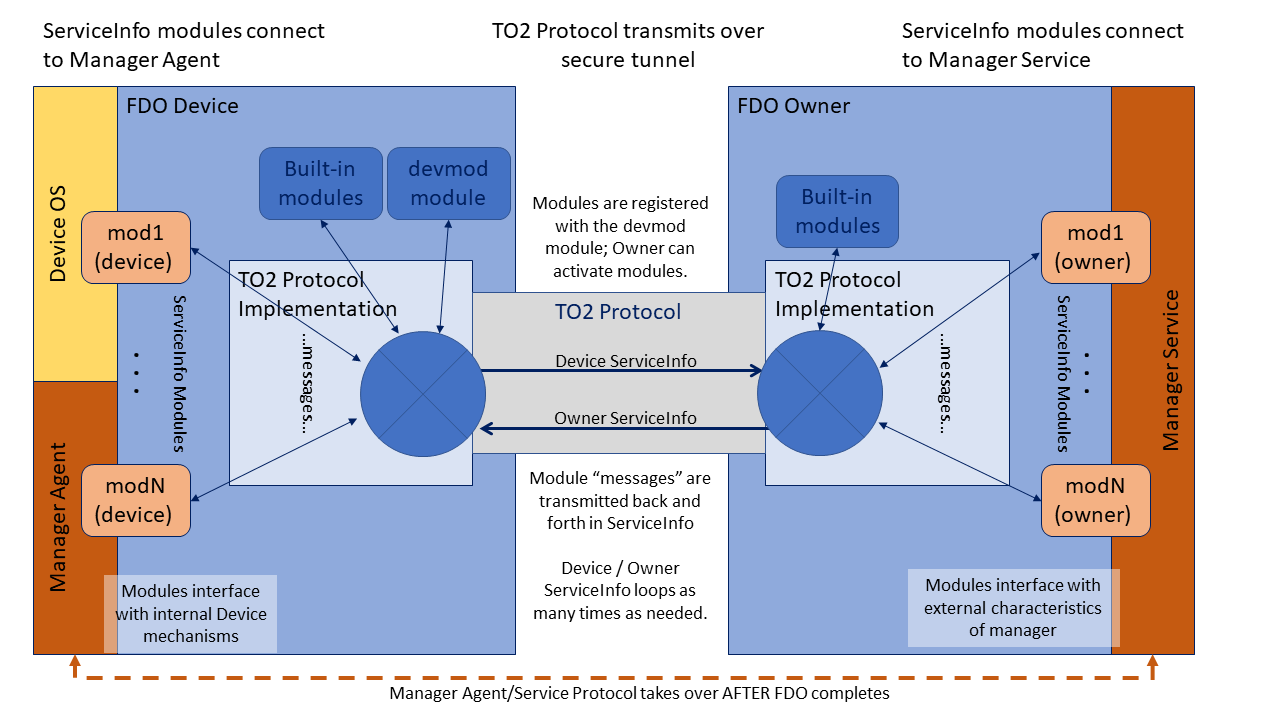
3.8.1. Mapping Messages to ServiceInfo
A module may have an arbitrary number of messages. There are no arrays, but numbered message names can be used to simulate their effect (mod:key1, mod:key2).
Since ServiceInfo messages are separated into one or more FIDO Device Onboard messages, it is possible to use the same message over and over again. Whether this is has a cumulative or repetitive effect is up to the module that interprets the messages (e.g., file:part might be repeated for successive parts, but tpm:certificate might be individual certificates).
Messages are processed in the order they appear in ServiceInfo.
The same message may also be repeated in a single ServiceInfo.
ServiceInfo does not have to be interpreted as it is parsed from the message. It is legal to buffer the entire ServiceInfo and interpret it all later. However, the messages must be interpreted in the same order.
In a given implementation it is possible to process the ServiceInfo variables as they arrive or in a batch. However, the order of interpretation of ServiceInfo messages MUST be preserved.
3.8.2. The devmod Module
The “devmod” module implements a set of messages to the FIDO Device Onboard Owner that identify the capabilities of the device. All FIDO Device Onboard Owners must implement this module, and FIDO Device Onboard Owner implementations must provide these messages to any module that asks for them. In addition all “devmod” messages are sent by the Device in the first Device ServiceInfo.
The following messages are defined in the devmod Module:
Table ‑. devmod Module Device Service Info Keys
| Device Service Info Key | Disposition | CBOR type | Meaning / Action |
|---|---|---|---|
| devmod:active | Required | bool (True) | Indicates the module is active. Devmod is required on all devices |
| devmod:os | Required | tstr | OS name (e.g., Linux) |
| devmod:arch | Required | tstr | Architecture name / instruction set (e.g., X86_64) |
| devmod:version | Required | tstr | Version of OS (e.g., “Ubuntu* 16.0.4LTS”) |
| devmod:device | Required | tstr | Model specifier for this FIDO Device Onboard Device, manufacturer specific |
| devmod:sn | Optional | tstr or bstr | Serial number for this FIDO Device Onboard Device, manufacturer specific |
| devmod:pathsep | Optional | tstr | Filename path separator, between the directory and sub-directory (e.g., ‘/’ or ‘\’) |
| devmod:sep | Required | tstr | Filename separator, that works to make lists of file names (e.g., ‘:’ or ‘;’) |
| devmod:nl | Optional | tstr | Newline sequence (e.g., '\r\n' or '\n') |
| devmod:tmp | Optional | tstr | Location of temporary directory, including terminating file separator (e.g., “/tmp”) |
| devmod:dir | Optional | tstr | Location of suggested installation directory, including terminating file separator (e.g., “.” or “/home/fdo” or “c:\Program Files\fdo”) |
| devmod:progenv | Optional | tstr | Programming environment. See Table 3‑22 (e.g., “bin:java:py3:py2”) |
| devmod:bin | Required | tstr | Either the same value as “arch”, or a list of machine formats that can be interpreted by this device, in preference order, separated by the “sep” value (e.g., “x86:X86_64”) |
| devmod:mudurl | Optional | tstr | URL for the Manufacturer Usage Description file that relates to this device |
| devmod:nummodules | Required | uint | Number of modules supported by this FIDO Device Onboard Device |
| devmod:modules | Required | [uint, uint, tstr1, tstr2, ...] | Enumerates the modules supported by this FIDO Device Onboard Device. The first element is an integer from zero to devmod:nummodules. The second element is the number of module names to return The subsequent elements are module names. During the initial Device ServiceInfo, the device sends the complete list of modules to the Owner. If the list is long, it might require more than one ServiceInfo message. |
The “progenv” key-value is used to indicate the Device’ capabilities for running programs. This is a list of tags, separated by the “sep” value, that indicates which programming environments are available and preferred on this platform. E.g., bin;perl;cmd means use system binary format (preferred), but Perl* is also supported, and Windows* CMD shell is also supported, but Perl is preferred over CMD.
The following tags are supported at present. Version numbers may be appended to the tag (as in py2 and py3).
Table ‑. devmod Module "progenv" Key Tags
| “progenv” tag | Meaning |
| bin | System-dependent most common binary format (the “arch” key-value may inform the format) |
| java | Java* class/jar (openJDK compatible) |
| js | Node.js* (Javascript*) |
| py2 | Python version 2 |
| py3 | Python version 3 |
| perl | Perl 5 |
| bash | Bourne shell |
| ksh | Korn shell |
| sh | *NIX system shell (whichever one it is) |
| cmd | Windows* CMD |
| psh | Windows Power Shell |
| vbs | Windows Visual Basic* Script |
| … | (Other specifiers may be defined on request. Contact the FIDO Device Onboard Enablement team) |
3.8.3. Module Selection
In some FIDO Device Onboard implementations, multiple modules can perform overlapping functions. Some modules may implement legacy versions of others (e.g., TPM versions) and some modules may control alternative IOT control techniques (e.g., MQTT versus CoAp). The FIDO Device Onboard Owner and FIDO Device Onboard Device need to negotiate to select the right set of modules.
In FIDO Device Onboard, module selection is as follows:
-
The Device sends a devmod:modules variable that lists modules initially supported by the FIDO Device Onboard Device. The Owner may inspect this list to determine modules to access.
A Device MAY allow the Owner to download a module during ServiceInfo, such that the module may be referenced by the Owner in the same FIDO Device Onboard session. The Device MAY update devmod:modules in this case. The mechanism to activate such a module is outside the scope of this document.
-
Owner ServiceInfo messages indicate the intent to access a module by sending an “active” message to the module (
[modname:active, True]). -
The Device ServiceInfo indicates which modules are selected by including an “active” message and provides device-side data for the modules from the Management Agent, as described below (§ 3.8.3.1 Module Activation/Deactivation in ServiceInfo).
-
The Owner ServiceInfo may deselect modules with its own “active” messages, and provides messages containing owner-side data from the Management Service.
3.8.3.1. Module Activation/Deactivation in ServiceInfo
Devices may export many modules, potentially with overlapping functions. The Owner must activate modules before using them, and may choose to deactivate particular modules (see example, below).
All Device modules implement a message modname:active to indicate
whether the module is active or not.
The Owner activates a module by sending it the message:
[modname:active, True]in OwnerServiceInfo. Once the module is activated, the Owner may send other messages to the module to perform actions on the Device.
The Owner may deactivate a module by sending it the message:
[modname:active, False]in OwnerServiceInfo.
The Device’s modname:active message argument is CBOR True if the module is
available, and CBOR False otherwise.
The Owner MUST send a [modname:active, True] message as its first message to each
module it references. It MAY send additional messages to the module
after the "active" message in the same ServiceInfo entry, before
determining if the module exists.
The Owner MAY send a [modname:active, False] message to a module,
indicating that the module is to be disabled. The Owner MUST send
no further messages to this module.
The Device SHOULD
prevent subsequent messages from accessing the referenced module
for the rest of the TO2 protocol instance.
Any other semantics associated with disabling a module are Device specific and outside the scope of this document.
The Device MUST respond to a reference to a non-existent module with a message:
[modname:active,False]The device SHOULD send this message only for the first message to a non-existent module, but MAY send this message on other references to such a module.
Except as regards the active message, above, the Device MUST ignore messages to modules it does not support. However, it must parse the CBOR for such messages in order to process subsequent messages in the ServiceInfo.
For example, a constrained FIDO Device Onboard Device may implement a management module and a firmware update module. The device send the current firmware version as a parameter in Device ServiceInfo. The FIDO Device Onboard Owner can decide either to accept this version of firmware and de-activate the firmware update module, or decide to update the firmware and de-activate the management module.
3.8.3.2. Module Execution and Errors
If possible, all module functions should complete in time to allow the FIDO Device Onboard operation to succeed or fail based on module operation, so that a module failure causes the entire FIDO Device Onboard operation to fail and be retried later. In some cases, the module cannot determine success criteria before FIDO Device Onboard completes (e.g., a firmware update module must restart the system to invoke the new software), and FIDO Device Onboard must complete “on faith” that all is well.
Any error in a module must cause the active FIDO Device Onboard session to fail with an error message. If the FIDO Device Onboard session has already completed (as described in the previous paragraph), a Device SHOULD store log information to allow subsequent error isolation. Such error processing and access to such error logs is outside the scope of FIDO Device Onboard.
3.8.3.3. Module Selection Using ServiceInfo
Module information in ServiceInfo may be used to indicate a preference for one module over another. For example, the FIDO Device Onboard Owner may indicate that a TPM2 module is preferred over a TPM1.2 module, even if both are supported by the Owner and the Device.
As an example, consider a device which exports 3 modules:
-
"tpm": a module to indicate the preference of one TPM version over another
-
"tpm2": a module to allocate keys from a TPM version 2
-
"tpm1.2" a module to allocate keys from a TPM version 1.2
In this example, IOT devices are originally distributed with TPM1.2, then later a new model is adopted, which uses TPM2. The Owner needs the device to allocate 3 key pairs for signing, based on the cryptography available; whichever version of TPM is present must allocate the appropriate key pairs.
The following ServiceInfo can instruct the legacy (TPM1.2) device to allocate 3 RSA key pairs, and the current (TPM2) device to allocate 3 ECDSA key pairs:
| index | ServiceInfoKey | ServiceInfoVal | meaning |
|---|---|---|---|
| 1 | "tpm-2:active" | True | Enable tpm-2 module |
| 2 | "tpm-1.2:active" | True | Enable tpm-1.2 module |
| 3 | "tpm-2:sgnKeys" | 3 | Allocate 3 TPM2 keys |
| 4 | "tpm-2:type" | "secp256r1" | TPM2 keys are ECDSA |
| 5 | "tpm-1.2:sgnKeys" | 6 | Allocate 3 TPM1.2 keys |
| 7 | "tpm-1.2:type" | "RSA3072" | TPM1.2 keys are RSA |
3.8.3.4. Examples
In the following examples, spaces are provided for clarity, and fragments of ServiceInfo are presented in pseudo JSON.
3.8.3.5. Expressing Values in Different Encodings
ServiceInfo:
[ ...[ 'mymod:options', 'foo, bar'] [ 'mymod:options', h’0393 a3 f3 '] ...]
These fragments define a message “mymod:options” with value “foo,bar”. The first gives the value in a text string (tstr), and the second is a byte string (bstr).
Which value is correct depends on the implementation of “mymod”.
3.8.3.6. Hypothetical File transfer (Owner ServiceInfo)
Owner ServiceInfo1:
Owner ServiceInfo2:[ [ 'binaryfile:active', True], [ 'binaryfile:name', 'myfile.tmp'], [ 'binaryfile:length', 722 ], [ 'binaryfile:data001 ', h'—*data-512 -bytes*—'] ]
[ [ 'binaryfile:data002 ', h'—*data-210 -bytes*—'], [ 'binaryfile:sha-384 ', h'—*data*—*48 -bytes*'] ]
In this example, a “binary file” module allows a file to be downloaded using the FIDO Device Onboard secure channel. The data001 and data002 variables need to be in separate ServiceInfo messages to keep message sizes small. A bstr is used to allow the module to generate a binary file. The last message allows the file transfer to be verified after it is stored in the filesystem, as an added integrity check.
Another way to accomplish file transfer would be to use an external HTTP connection. For example:
Owner ServiceInfo:
[ [ 'wget:active', True], [ 'wget:filename', 'myfile.tmp'], [ 'wget:url', 'http://myhost/myfile.tmp'], [ 'wget:sha-384 ', h'—*data*—*48 -bytes*—'] ]
In this case, the file is transferred using a separate connection, perhaps at OS level. If the file is confidential, ‘https:’ could be used instead of ‘http:’.
Both these techniques are valid in FIDO Device Onboard, and represent two sides of a tradeoff. Using the FIDO Device Onboard channel, a small file can be transferred without needing a parallel network connection (see section 5.6.1 for limitations on the FIDO Device Onboard channel size). However, the same file might be transferred much faster using an optimized HTTP implementation, and might not require the confidentiality built into FIDO Device Onboard (e.g., the file contents might be posted on a public Internet site). Table 3‑23 discusses the tradeoff.
Table ‑. Comparison of Transferring a File Using FIDO Device Onboard Channel or Independent Channel
| File Transfer Using FIDO Device Onboard Channel | File Transfer Using HTTP Mechanism |
| Performance based on FIDO Device Onboard protocol (slow for file large data) | Performance based on HTTP or HTTPS, designed for streaming large amounts of data. Second stream required. |
| Can download large amounts of bulk data or programs (limited to the number of ServiceInfo iterations) | Can download arbitrary amounts of bulk data or programs |
| Data can be stored in a file | Data can be stored in a file |
| Data can be executed as a program | Data can be executed as a program |
| Data is encrypted using FIDO Device Onboard channel | Data is encrypted only if HTTPS is used. |
| Data is verified using FIDO Device Onboard channel | Data can verified by the module if a hash of contents (e.g., SHA384) is included |
3.8.3.7. Hypothetical Direct Code Execution
Owner ServiceInfo:
[ [ 'code:active', True], [ 'code:architecture', 'x86 _64 '], [ 'code:length':'512 '], [ 'code:machinecode001 ', '—*data-512 -bytes*—'] ]
In this example, a module permits loading and executing machine code (this might be needed on a MCU). Obviously, this requires a high degree of trust in the FIDO Device Onboard implementation, and perhaps an ability to execute code in a sandbox.
3.8.4. Implementation Notes
This section is non-normative.
An FIDO Device Onboard implementation may implement ServiceInfo in a variety of ways. It is recommended that FIDO Device Onboard implementations create a ServiceInfo interface on both Device and Owner side, that allows an easy plug-in mechanism.
On the Owner side, a dynamic plug-in mechanism may by easier to maintain.
On the Device side, a statically linked or compiled mechanism may be required due to system constraints. However, a more capable Device that runs Linux OS might be able to implement a flexible scripted mechanism similar to Linux init.d.
Constrained Devices must still parse ServiceInfo messages, but may discard them if the module or message is not supported.
4. Data Transmission
4.1. Message Format
All data is transmitted using Messages. Data may also be persisted or interchanged using messages, although a more compact form of the message might be used for long-term storage; for example, a persisted type might be compressed or re-encoded in a system-dependent binary format.
A message has 4 elements:
-
A length
-
A message type, which acts to identify the message body
-
Protocol version: the version of the transmitted ("wire") protocol
-
A particular protocol message body, associated with the message ID, defined in the context of the protocol
Messages may be transmitted or forwarded using a variety of communications mechanisms, such as API’s, physical media, and protocols that layer on physical media. The encapsulation of the message can vary, depending on the media in use. For example, an HTTP message includes a content length in a specific format.
The protocol message body is always transmitted so as to recreate the same logically contiguous message on the other end of communications. The other parameters may be encoded within the communications medium. Of particular interest are these cases:
-
When FIDO Device Onboard protocols are transmitted using a reliable stream protocol, or a technology that provides a similar service.
-
When FIDO Device Onboard protocols are transmitted using HTTP-like protocols (i.e., HTTP, HTTPS or CoAP).
The StreamMsg type (§ 3.3 Composite Types) includes the entire message format, with all elements included. A space is provided for protocol-specific information, and the message body appears separately.
The array header and message length are designed to have a constrained length in CBOR format, which may be read first by a low level driver. The low level driver reads the first 4 bytes of a message. The encoding guarantees that all messages have at least 4 bytes, and that message length is completely contained in these first 4 bytes. The low level driver can use this information to read the rest of the message.
The StreamMsg type has been created in a way that allows a FIDO Device Onboard implementation to present a message to the code that processes it in a uniform manner, independent of protocol transmission. However, applications can choose to use another format if it is more convenient.
FIDO Device Onboard implementations SHOULD create a StreamMsg structure for message interpretation, regardless of the way the FIDO Device Onboard connection is actually transmitted.
4.2. Transmission of Messages over a Stream Protocol
In some cases, messages are transmitted over a stream or datagram protocol. This is a protocol that reliably transmits a stream of data with no external or out-of-band information. In this case, all message data must be encapsulated in a single protocol data unit (PDU) that encapsulates a CBOR-encoded StreamMsg type.
When a stream protocol (such as TCP or TLS) is used as the transport FIDO Device Onboard protocols, the protocol proceeds as follows:
-
The Device always calls out as the stream client.
-
The Rendezvous Server always acts as the stream server.
-
The Owner Onboarding Service acts as stream client for Transfer Ownership Protocol 0 TO0—interacting with the Rendezvous Server) and as stream server for Transfer Ownership Protocol 2 (TO2—interacting with the device).
-
Internet-based protocols normally use standard protocols TCP or UDP port (e.g., HTTP on port 80, HTTPS on port 443). However, for testing, or where needed, other ports may be used.
-
For all reliable stream protocols, StreamMsg items are transmitted in the stream verbatim, without a separate messaging layer.
-
The stream is kept open until the last message has been transmitted, then dropped using the normal stream close (e.g., TCP FIN).
-
The stream connection must be adjusted to handle expected processing delays without dropping the connection. In the case of a TCP stream (direct or underlying), the client and server must configure their TCP implementation to send “keep-alives” frequently enough to keep the connection alive for the entire protocol transaction, including all stateful routers and firewalls that might be in the connection path. This is particularly an issue if either the client or the server takes a long delay to send some messages.
-
Dropping a stream connection constitutes a failure of the protocol, causing the client to restart as mandated by this specification. For example, a Device will handle a failure of a TO2 protocol by restarting with the next identified host in the Rendezvous protocol, and initiating TO1.
4.3. Transmission of Messages over the HTTP-like Protocols
This section describes how to transmit FIDO Device Onboard over a sequence of HTTP-like transactions, sometimes called "RESTful" protocols. This section applies to several such protocols, including HTTP, HTTPS and CoAP. FIDO Device Onboard is not itself a RESTful protocol, since it maintains state between client and server across message boundaries. However, it is useful to use RESTful protocols to transmit FIDO Device Onboard messages.
In what follows, HTTP is used to characterize FIDO Device Onboard behavior. Other HTTP-like protocols use the same rules.
When HTTP (or an HTTP-like) protocol is used as transport for JSON messages, the protocol proceeds as follows:
-
The HTTP client always uses an HTTP POST. The content type is
application/cbor. -
The HTTP server listens on a standard port for the transport protocol. (HTTP: TCP/80, TLS: TCP/443)
Non-standard ports MAY be used if needed for special deployment circumstances, such as when multiple servers share a common IP address.
-
The Device interprets the RendezvousInfo and implements the TO1 protocol using HTTP.
-
Each HTTP request-response interaction corresponds to a pair of messages.
-
The first message body is delivered in the POST body.
-
The second message is delivered as the entire POST response with status code 200 OK [RFC2616], unless it is an error message.
-
The second message contains the message type as the HTTP header with field-name: "Message-Type:" and field-value: the numeric message type given in this document. An error message MAY omit the "Message-Type" header. Example: "Message-Type: 21".
-
The length of the message is derived from the Content-Length field.
-
The URL for the message is of the form:
/fdo/100/msg/msgtype
Where the first part, “/fdo/” is verbatim; the number “10” is the protocol version (major version (1) * 100 + minor version 0); the string “/msg” is verbatim, and msgtype is the message type associated with the protocol message.
-
-
On first message, the HTTP server allocates a token, which must be maintained by the HTTP client for the duration of the connection.
-
The token is transmitted in the HTTP “Authorization” header.
-
The form of the token is implementation-specific. The simplest token is just a random number chosen to be unique from other tokens. A JSON Web Token (JWT) or CBOR Web Token (CWT) might also be used.
-
The purpose of the token is to link HTTP calls to their protocol context within the message stream defined by the FIDO Device Onboard Protocols. For example, a Java implementation of FIDO Device Onboard protocols might use a Java object to store connection state. The handler for a subsequent HTTP message can find this stored state by looking it up using the token as a key.
-
After the TO1 protocol is completed, the Device chooses the DNS/IP address, port and protocol from the RVTO2Addr array delivered in the TO1 protocol. The Device SHOULD choose the lowest indexed RVTO2AddrEntry it is able to implement, in order to reflect the preference of the Owner. However, the Device MAY choose the entries in any order if it has its own preferences (e.g., protocol resource usage in a constrained Device).
If a DNS name is present in a selected RVTO2AddrEntry, the DNS lookup is performed first, and all resolved IP addresses are tried before the given IP address is tried. If the given IP address was one of the IP addresses returned by DNS, it does not have to be tried separately (once is enough).
Based on these and the above rules, the Device implements the TO2 protocol.
-
An FIDO Device Onboard Device MAY support only TCP (e.g., HTTP but not HTTPS), relying on FIDO Device Onboard for all transmission security. A proxy may be used to encapsulate TCP from constrained devices into TLS. Although this does not change the security posture of the connection, it may be useful for connecting to the largest possible number of Owner sites.
The FIDO Device Onboard implementation has some latitude in both the form of the authorization token and how this token gets allocated for FIDO Device Onboard protocols. In the typical (recommended) case, there is no initial authorization:
-
The initial HTTP request from the Device has an empty Authorization header or no such header. FIDO Device Onboard protocols perform their own authorization within the message layer.
-
The Rendezvous Server detects such a header as a request for a new connection, and allocates a new token and associates it with the protocol context.
-
The Device saves the token and uses it on subsequent requests within the protocol, but not across protocols. An example is when TO1 uses one token, and TO2 uses a different token.
-
The Rendezvous Server uses the token to look up the protocol context so that each subsequent message is processed correctly.
If the Rendezvous Server wishes to obtain a token using specific HTTP credentials, these must be programmed into the device, then transmitted with or before the first FIDO Device Onboard HTTP request. How this might be done is outside the scope of this document.
4.3.1. Maintenance of HTTP Connections
When transmitting messages across HTTP request-response pairs, the client and server must take into account the possibility that the underlying network connection may time out between HTTP messages. This is a problem if the time between a given HTTP message and its response (i.e., a POST and the POST response) is long or if the time between messages is long.
In general, each FIDO Device Onboard protocol may send HTTP request-response messages across a single TCP stream (or TLS stream for HTTPS). We require that the TCP server side (the Owner or the Rendezvous Server) either respond to messages within one or two seconds, or generate TCP keep-alives sufficient to keep the connection open.
In the case of the TO1 and TO2 Protocols, the client is the Device, which might be running on a constrained systemn. In this case, some of cryptographic operations may take long enough for the underlying TCP connection to time out between messages. The client must be robust in its ability to restore TCP / TLS connections for each protocol transaction.
It is legal for the client to open a new TCP connection for each HTTP request, although it is recommended that the connection be used for multiple requests where possible.
4.4. Encrypted Message Body
Transfer Ownership 2 Protocol (TO2) includes a key exchange (see § 3.6 Key Exchange in the TO2 Protocol), which generates a session encryption key (SEK) and a session verification key (SVK); or a single session encryption and verification key (SEVK). Subsequent message bodies in this protocol are confidentiality and integrity protected:
-
Using encryption with the session encryption key (Cipher[SEK]) and subsequent integrity protection using the verification key (HMAC[SVK]).
-
Using encryption and integrity protection via an authenticated encryption technique supported by COSE, such as AES-GCM [SP800-38D] or AES-CCM [SP800-38C]. The key material for these is SEVK.
An encrypted message has the following format:
-
A message header, as per: § 2.1 Message Passing Protocol
-
A message body, which is a COSE object whose payload is the message, encrypted and integrity protected by COSE primitives.
CDDL
EncryptedMessage /= (
Simple: EncryptedMessage,
Composed: EncThenMacMessage
)
EncryptedMessage = #6.16(EMBlock)
;;Simple encrypted message, using one COSE
;; (authenticated) encryption mechanism.
EMBlock = [
protected: { 1 :COSEEncType },
unprotected : { COSEUnProtFields }
payload : ProtocolMessage
signature : bstr
]
;; Non-Simple is Encrypt-then-Mac, implemented as
;; an HMAC (COSE_Mac0) with a AES (COSE_Encrypt0) inside
EncThenMacMessage = #6.17(HMacOuterBlock) ;; MAC0
ETMOuterBlock = [
protected: bstr .cbor ETMMacType,
unprotected: {},
payload : bstr .cbor ETMPayloadTag,
hmac : bstr
]
ETMMacType = { 1: MacType }
ETMPayloadTag = #6.16(ETMInnerBlock)
ETMInnerBlock = [
protected: { 1 :AESPlainType },
unprotected : { 5 :AESIV }
payload : ProtocolMessage
signature : bstr
]
MacType = HMAC-SHA256 / HMAC-SHA384
HMAC-SHA256 => 5
HMAC-SHA384 => 6
AESPlainType = ( COSEAES128CBC / COSEAES256CBC / COSEAES128CTR / COSEAES256CTR )
AESIV = bstr .size 16
# Encrypt Then Mac suites
ETMSuites /= (
"AES128/CTR/HMAC-SHA256",
"AES128/CBC/HMAC-SHA256",
"AES256/CTR/HMAC-SHA386",
"AES256/CBC/HMAC-SHA384"
)
CipherSuites => ( COSETypes / AESPlainType / ETMSuites )
# Placeholder for values defined in the COSE specification
COSEEncType = A128GCM / A256GCM / AES-CCM-64-128-128 / AES-CCM-64-128-256 ...
AES128GCM, AES256GCM, AES-CCM-16-128-128, AES-CCM-16-128-256 are defined in the COSE specification [RFC8152].
With respect to AES CCM modes, note that the message size for FIDO Device Onboard is restricted to 2^16 bytes, so a AES CCM mode with L=16 is acceptable. See [RFC3610]
COSEEncType indicates encryption mechanisms from the COSE specification [RFC8152].
The given list is exemplary; all encryption types defined in the COSE spec are permitted to be used with
FIDO Device Onboard. COSEUnProtFields indicates unprotected header fields
chosen from [RFC8152], such as IV type 5,
defined within the Generic_Headers CDDL object.
The mechanism of EncThenMac is a common
encrypt-then-mac
operation, created by composing COSE messages. This mechanism is
provided for legacy cryptographic engines which do not yet support
authenticated encryption as a single operation. In pseudo-JSON, this
composed structure has the following form:
Geof Note: AES-CTR-or-CBC is not defined by COSE, we need to define it.
Example:
COSE_Mac0 [ { 1:5}, # protected: alg:SHA256 {}, # unprotected COSE_Encrypt0 [ { 1:AESPlainType} # protected{ 5:h'--*iv*--'}, #unprotected h'--*AES*-*encrypted*-*CBOR*--'], h'--*hmac*-*bytes*---']
Table ‑.
| Cipher Suite Name (see TO2.HelloDevice) | Initialization Vector (IVData.iv in "ct" message header) | Notes |
| A128GCM A256GCM AES-CCM-64-128-128 AES-CCM-64-128-256 | Defined as per COSE specification. Other COSE encryption modes are also supported. |
COSE encryption modes are preferred, where available.
KDF uses HMAC-SHA256 |
| AES128/CTR/HMAC-SHA256 |
The IV for AES CTR Mode is 16 bytes long in big-endian byte order, where:
The random data source must be a cryptographically strong pseudo random number generator (CSPRNG) or a true random number generator (TNRG). |
This is the preferred encrypt-then-mac cipher suite for FIDO Device Onboard for
128-bit keys. Other suites are provided for situations where Device
implementations cannot use this suite.
AES in Counter Mode [6] with 128 bit key using the SEK
from key exchange.
KDF uses HMAC-SHA256 |
| AES128/CBC/HMAC-SHA256 | IV is 16 bytes containing random data, to use as initialization vector for CBC mode. The random data must be freshly generated for every encrypted message. The random data source must be a crypographically strong pseudo random number generator (CSPRNG) or a true random number generator (TNRG). |
AES in Cipher Block Chaining (CBC) Mode [3] with PKCS#7 [17]
padding. The key is the SEK from key exchange.
Implementation notes:
It is recognized that the first item is hard to achieve in general, but FIDO Device Onboard risk is low in this area, because any decryption error will cause the connection to be torn down. KDF uses HMAC-SHA256 |
| AES256/CTR/HMAC-SHA384 |
The IV for AES CTR Mode is 16 bytes long in big-endian byte order, where:
The random data source must be a cryptographically strong pseudo random number generator (CSPRNG) or a true random number generator (TNRG). |
This is the preferred encrypt-then-mac
cipher suite for FIDO Device Onboard for 256-bit keys. Other suites are provided for
situations where Device implementations cannot use this suite.
AES in Counter Mode [6]
with 256 bit key using the SEK from key exchange.
KDF uses HMAC-SHA384 |
| AES256/CBC/HMAC-SHA384 | IV is 16 bytes containing random data, to use as initialization vector for CBC mode. The random data must be freshly generated for every encrypted message. The random data source must be crypographically strong pseudo random number generator (CSPRNG) or a true random number generator (TNRG) |
AES-256 in Cipher Block
Chaining (CBC) Mode [15] with PKCS#7[16] padding. The key is the SEK from
key exchange.
Implementation notes:
It is recognized that the item is hard to achieve in general, but FIDO Device Onboard risk is low in this area, because any decryption error causes the connection to be torn down. KDF uses HMAC-SHA384 |
5. Detailed Protocol Description
This section defines protocol messages and interactions.
Composite types described in the tables in section § 3.3 Composite Types are used freely.
5.1. General Messages
5.1.1. Error - Type 255
Message Body:
ErrorMessage = [
    EMErrorCode: uint16,   ;; Error code
    EMPrevMsgID: uint8,    ;; Message ID of the previous message
    EMErrorStr:  tstr,     ;; Error string
    EMErrorTs:   timestamp,;; UTC timestamp
    EMErrorUuid: correlationId ;; Unique Uuid associated with this request
]
timestamp = null / UTCStr / UTCInt / TIME_T
UTCStr = #6.0(tstr)
UTCInt = #6.1(uint)
TIMET  = #6.1(uint)
correlationId = uint
HTTP Context:
-
When transmitted as HTTP response:
-
HTTP response is status code: 500 Internal Service Error [RFC2616]
-
HTTP response includes authentication token, if one is active
-
HTTP response body contains ErrorMessage
-
-
When transmitted as HTTP request:
-
HTTP request is: POST /fdo/100/msg/255
-
Message type is 255 (Error)
-
HTTP message contains authentication token, if one is active
-
HTTP message body contains ErrorMessage
-
Message Meaning:
The error message indicates that the previous protocol message could not be processed. The error message is a “catch-all” whenever processing cannot continue. This includes protocol errors and any trust or security violations.
The FIDO Device Onboard protocol is always terminated after an error message (and retries, automatically, as per RendezvousInfo), and all FIDO Device Onboard error conditions send an error message. However, security errors might not indicate the exact cause of the problem, if this would cause a security issue.
The contents of the error message are intended to help diagnose the error. The “EMErrorCode” is an error code, please see following section, Error Code Values, for detailed information. The “EMPrevMsgID” gives the message ID of the previous message, making it easier to put the error into context. The “EMErrorStr” tag gives a string suitable for logging about the error.
The string in the “EMErrorStr” tag must not include security details that are inappropriate for logging, such as a specific security condition, or any key or password information.
The values EMErrorTS and EMErrorUuid are intended to expedite diagnosis of problems, especially between cloud-based entities where large logs must be searched. In a typical scenario, an endpoint generates a UUID for each request and includes it in column of each event or trace logged throughout processing for that request. The combination of UUID and the time of the transaction help to find the log item and its context.
EMErrorTS and EMErrorID may be CBOR Null if there is no appropriate value. This may occur in Devicee based implementations. In some Devices, a time value may exist that is not correlated to UTC time, but might still be useful. The TIMET choice is intended to remove the UTC restriction and allow a Device-local time value to be used.
If the problem is found in a HTTP request, the ERROR message is sent as HTTP response. The body of the response is a FIDO Device Onboard message with message type 255, and “EMErrorStr” indicates the message type of the HTTP request message. The flow is as follows:
-
HTTP request: POST /fdo/100/msg/X, msg type = X
-
HTTP error message in response, as described above
-
FIDO Device Onboard terminates in error on both sides
If the problem is found in a HTTP response, the ERROR message is sent as a new HTTP request, POST /fdo/100/msg/255, and the “EMPrevMsgID” indicates the message type of the previous HTTP response message. The authentication token from the previous HTTP request appears in the HTTP request containing the ERROR message. Since the ERROR message terminates the FIDO Device Onboard protocol, the HTTP response to an ERROR message is an HTTP empty message (zero length). The flow is as follows:
-
HTTP request: POST /fdo/100/msg/Y, msg type = Y (for any message type Y)
-
HTTP response: msg type = X
-
HTTP request, error message in request, as described above
-
HTTP response: <zero length>
-
FIDO Device Onboard terminates in error on both sides
ERROR messages are never retransmitted, and an ERROR message must never generate an ERROR message in response.
5.1.1.1. Error Code Values
Table ‑. Error Codes
| Error Code (EC) | Internal Name | Generated by Message | Description |
| 001 | INVALID_JWT_TOKEN | DI.SetHMAC TO0.OwnerSign TO1.ProveToRV TO2.HelloDevice TO2.GetOVNextEntry TO2.ProveDevice TO2.NextDeviceServiceInfo TO2.Done | JWT token is missing or authorization header value does not start with 'Bearer'. Each token has its own validity period, server rejects expired tokens. Server failed to parse JWT token or JWT signature did not verify correctly. The JWT token refers to the token mentioned in section 4.3 (which is not required by protocol to be a JWT token). The error message applies to non-JWT tokens, as well. |
| 002 | INVALID_OWNERSHIP_VOUCHER | TO0.OwnerSign | Ownership Voucher is invalid: One of Ownership Voucher verification checks has failed. Precise information is not returned to the client but saved only in service logs. |
| 003 | INVALID_OWNER_SIGN_BODY | TO0.OwnerSign | Verification of signature of owner message failed. TO0.OwnerSign message is signed by the final owner (using key signed by the last Ownership Voucher entry). This error is returned in case that signature is invalid. |
| 004 | INVALID_IP_ADDRESS | TO0.OwnerSign | IP address is invalid. Bytes that are provided in the request do not represent a valid IPv4/IPv6 address. |
| 005 | INVALID_GUID | TO0.OwnerSign | GUID is invalid. Bytes that are provided in the request do not represent a proper GUID. |
| 006 | RESOURCE_NOT_FOUND | TO1.HelloRV TO2.HelloDevice | The owner connection info for GUID is not found. TO0 Protocol wasn’t properly executed for the specified GUID or information that was stored in database has expired and/or has been removed. |
| 100 | MESSAGE_BODY_ERROR | DI.AppStart DI.SetHMAC TO0.Hello TO0.OwnerSign TO1.HelloRV TO1.ProveToRV TO2.HelloDevice TO2.GetOVNextEntry TO2.ProveDevice TO2.NextDeviceServiceInfo TO2.GetNextOwnerServiceInfo TO2.Done | Message Body is structurally unsound: JSON parse error, or valid JSON, but is not mapping to the expected Secure Device Onboard type (see 4.6) |
| 101 | INVALID_MESSAGE_ERROR | TO0.OwnerSign TO1.HelloRV TO1.ProveToRV TO2.HelloDevice TO2.GetOVNextEntry TO2.ProveDevice TO2.NextDeviceServiceInfo TO2.GetNextOwnerServiceInfo | Message structurally sound, but failed validation tests. The nonce didn’t match, signature didn’t verify, hash, or mac didn’t verify, index out of bounds, etc... |
| 102 | CRED_REUSE_ERROR | TO2.SetupDevice | Credential reuse rejected. |
| 500 | INTERNAL_SERVER_ERROR | DI.AppStart DI.SetHMAC TO0.Hello TO0.OwnerSign TO1.HelloRV TO1.ProveToRV TO2.HelloDevice TO2.GetOVNextEntry TO2.ProveDevice TO2.NextDeviceServiceInfo TO2.GetNextOwnerServiceInfo TO2.Done | Something went wrong which couldn’t be classified otherwise. (This was chosen to match the HTTP 500 error code.) |
5.2. Device Initialize Protocol (DI)
The Device Initialize Protocol a non-normative protocol, and may be replaced by any protocol that achieves the same end-state of storing the Device Credentials in the device and creating the Ownership Proxy to complement these credentials.
The Device Initialize Protocol (DI) serves to set the manufacturer and owner of the device in the ROE. It is assumed to be performed at device manufacture time.
This protocol uses a Trust On First Use (TOFU) trust model, consistent with the FIDO Device Onboard assumption that the manufacturing environment is trusted.
It is possible to implement a more restricted trust model for the DI Protocol by embedding a public key into the ROE, with the ROE owner providing signing (or at least CA) services to the manufacturer.
The DI Protocol runs between a manufacturing support station, which contains the FIDO Device Onboard Manufacturing Component, and the Device ROE.
The Device is assumed to be running with some other kind of support software, which is able to access the ROE and provide communications services for it. For example, the device may be PXE-booted into a RAM-based Linux system, with features to access the ROE. It is assumed that this software is able to determine from its environment the IP address for the manufacturing support station.
Some devices may be initialized without normal CPU "startup". These devices can be initialized for FIDO Device Onboard using other techniques.
Before the DI protocol is run, it is assumed that:
-
The Device has a key pair installed, that can be used to run FIDO Device Onboard.
-
The manufacturer has a copy of the Device public key and has created a Device certificate chain.
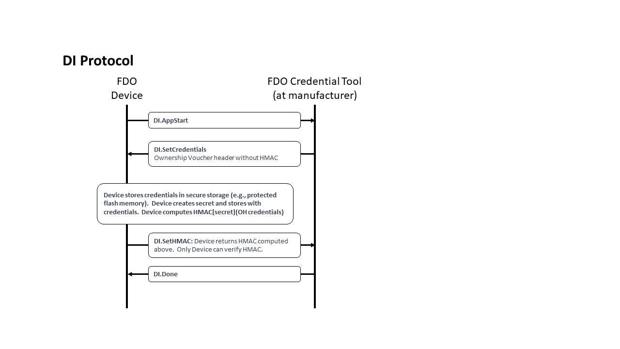
CDDL
DIProtocolMessages /= (
    DI.AppStart,
    DI.SetCredentials,
    DI.SetHMAC,
    DI.Done
)
5.2.1. DIAppStart, Type 10
From Device ROE to Manufacturer:
The App Start message starts talking to the ROE application to start. Downloading, verifying, and starting the ROE application is outside the scope of this document.
Message Format:
DI.AppStart = [
    DeviceMfgInfo
]
DeviceMfgInfo = cborSimpleType
HTTP Context:
POST /fdo/100/msg/10
Message Meaning:
Start the process of taking initial ownership of the device.
If available, the device may include a serial number or other identifying mark
from the hardware in this message, using DeviceMfgInfo. This is intended to help
the manufacturing station to index FIDO Device Onboard information with other information
available to the manufacturer. If no such information is available, DeviceMfgInfo is sent with a cbor null value.
The manufacturing station SHOULD be able to accept any legal value of DeviceMfgInfo, even if the value cannot be interpreted.
5.2.2. DISetCredentials, Type 11
From Manufacturer to Device ROE:
Message Format:
DI.SetCredentials = [
    OVHeader
]
HTTP Context:
-
POST response
-
includes authorization token
Message Meaning:
The manufacturing station sends credentials to the Device ROE. The credentials
in OVHeader are identical to the OVHeader field of the Ownership Voucher. Some
additional credentials allow the original manufacturer of the device to be
determined across future ownership transfers.
The manufacturing
station computes the Hash of the device certificate chain (provided by the
manufacturer to the manufacturing tool) and includes the Hash as OVHeader.OVDevCertChainHashOrNull in the
message. When the device uses Intel® EPID root of trust, OVHeader.OVDevCertChainHashOrNull may
be CBOR null.
The manufacturing station typically will use the DeviceMfgInfo determine
information for OVHeader.OVRendezvousInfo, OVHeader.OVDeviceInfo and OVHeader.PublicKey. The OVHeader.OVGuid field (GUID) shall be a
secure-randomly created unique identifier and not derived in any way from
device-specific information to ensure the privacy of the protocol. The Device
ROE allocates a secret, stores this information in the Device ROE within
the DeviceCredential, along with the secret. A hash of the public key OVHeader.OVPubKey is stored as a DeviceCredential.DCPubKeyHash.
The Device ROE also computes an HMAC based on the above secret and the entire contents of this message body (including the brace brackets). This HMAC is used in the next message.
Potential uses for DeviceMfgInfo:
-
model number and/or serial number of the device, used as a database search key
-
certificate chain for device key to be used with FIDO Device Onboard, where the device stores part of this chain in an earlier stage of manufacturing.
5.2.3. DI.SetHMAC, Type 12
From Device ROE to Manufacturer:
Message Format:
DI.SetHMAC = [
    Hmac
]
HTTP Context:
POST /fdo/100/msg/12
Message Meaning:
The device ROE returns the HMAC of the internal secret and the DI.SetCredentials.OVHeader tag, as mentioned above. The manufacturer combines this HMAC with its own transmitted information to create an Ownership Voucher with zero entries.
5.2.4. DIDone, Type 13
From Manufacturer to Device ROE:
Message Body:
DI.Done = [] ;; empty message
HTTP Context:
-
POST response with token
Message Meaning:
Indicates successful completion of the DI protocol. Before this message is sent, credentials associated with the device should be recoverably persisted in the manufacturing backend.
Upon receipt of this message, the device persists all information associated with the Device Initialization protocol.
5.3. Transfer Ownership Protocol 0 (TO0)
The function of Transfer Ownership Protocol 0 (TO0) is to register the new
owner’s current Internet location with the Rendezvous Server under the GUID of
the device being registered. This location is formatted into a 'blob'
of data, which includes an array of type RVTo2Addr with addressing
options for the Device. The Rendezvous Server negotiates a length of time
during which it will remember the rendezvous 'blob.' If the new
owner does not receive a device transfer of ownership within this time, it must
re-connect to the Rendezvous Server to repeat Transfer Ownership Protocol 0.
Transfer Ownership Protocol 0 MUST be implemented as a normative interface to each Rendezvous Server. This normative requirement ensures interoperability between Owners and Rendezvous Servers.
However, any given Owner and given Rendezvous Server may implement any interface or protocol to register the rendezvous information, instead of using the TO0 protocol, so long as the state of the Rendezvous Server with respect to the Transfer Ownership Protocol 1 (TO1) is identical to that generated by the TO0 protocol specified here.
The protocol begins when the Owner Onboarding Service opens a connection to the Rendezvous Server as is given in the Ownership Voucher.
The preferred protocol to use is TLS with server authentication only. The necessary client authentication is provided by the ownership voucher.
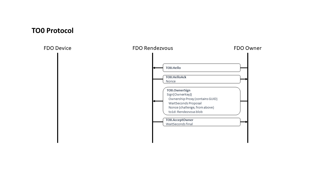
CDDL
TO0ProtocolMessages = (
    TO0.Hello,
    TO0.HelloAck,
    TO0.OwnerSign,
    TO0.AcceptOwner
)
5.3.1. TO0.Hello, Type 20
From Owner Onboarding Service to Rendezvous Server
Message Format:
TO0.Hello = [] ;; -empty array-
HTTP Context:
POST /fdo/100/msg/20
Message Meaning:
Initiates the TO0 Protocol, requests a Hello Ack nonce.
5.3.2. TO0.HelloAck, Type 21
From Rendezvous Server to Owner Onboarding Service
Message Format:
CDDL
TO0.HelloAck = [
    Nonce3
]
HTTP Context:
-
POST response
-
includes authorization token
Message Meaning:
Requests proof of the Ownership Voucher. Nonce3 is returned in TO0.OwnerSign.
5.3.3. TO0.OwnerSign, Type 22
From Owner Onboarding Service to Rendezvous Server
Message Format:
CDDL
TO0.OwnerSign = [
    to0d,    ;; TO0 protocol parameters, not used in TO1
    to1d     ;; TO1 blob being provided from Owner
]
;; to0d is covered by the signature of to1d, using a hash
to0d = [
    OwnershipVoucher, ;; Ownership Voucher (complete)
    WaitSeconds,      ;; how many seconds to wait.
    Nonce3            ;; Freshness of signature
]
WaitSeconds = uint32
;; to1d is the "rendezvous blob" that the Owner sends to the
;; Device via the rendezvous server.
;; To1d is used for both the to0 protocol and the to1 protocol
to1d = CoseSignature
to1dBlobPayload = [
    to1dRV:       RVTO2Addr, ;; choices to access TO2 protocol
    to1dTo0dHash: Hash       ;; Hash of to0d from same to0 message
]
$COSEPayloads /= (
    to1dBlobPayload
)
HTTP Context:
POST /fdo/100/msg/22
Message Meaning:
The new owner demonstrates its credentials for a given GUID by providing the
Ownership Voucher and signing with the Owner Key. In addition, the owner
provides the network address(s) where it is waiting for a Device to connect
(entries in the RVTO2Addr array)
and upper bound of how long it is willing to
wait (to0d.WaitSeconds). The wait time is negotiated with the server, see TO0.AcceptOwner.WaitSeconds. After the negotiated wait time passes, the owner must re-run
the TO0 Protocol to refresh its mapping.
The Ownership Voucher is given in to0d.OwnershipVoucher as a single object. The Ownership
Voucher must have at least one entry, i.e., len(to0d.OwnershipVoucher.OVEntries) > 0, or the
Rendezvous Server MUST fail the connection. The Rendezvous Server cannot verify an ownership voucher with zero
entries. The Rendezvous Server MAY
also restrict the maximum number of entries it is willing to accept, to prevent
DoS attacks. The current recommended maximum is ten entries. The
Rendezvous Server MAY also restrict the maximum blob size it is
willing to accept. It is recommended that Rendezvous Servers accept a
RVTO2Addr array of at least 3 entries.
The encoding of this message is divided into two objects: to0d and to1d, which are linked by the hash to1dTo0dHash inside of to1d. The object to0d contains fields that are only used in the TO0 Protocol, and the object to1d contains fields that are also used in the TO1 Protocol.
The fields in to0d are:
to0d.OwnershipVoucher:
|
The entire Ownership Voucher. The Owner Key is given in the last
OwnershipVoucherEntry. The Owner key is used to verify the COSE
signature in |
to0d.WaitSeconds:
|
The wait time offered by the Owner, which is adjusted and confirmed in |
to0d.Nonce3:
|
A copy of |
The to1d object is a signed "blob" that indicates a network
address (RVTO2Addr) where the
Device can find a prospective Owner for the TO2 Protocol. The entire object is stored by the
Rendezvous Server and returned verbatim to the Device in the TO1
Protocol. This value is verified by the Device at a later time (§ 5.5.3 TO2.ProveOVHdr, Type 61).
The fields in to1d are as follows. RVTO2AddrEntry fields are
listed after an elipsis, such as: to1d...RVIP instead of to1d.RVTO2Addr.RVTO2AddrEntry[i].RVIP
to1d...RVIP:
|
An internet address where the Owner is listening for a TO2
connection. It may be CBOR null if only |
to1d...RVDNS:
|
A DNS name where the Owner is listening for a TO2 connection.
Any IP address resolved by the DNS name must be equivalently able to process
the TO2 connection. A CBOR null may be used if only the |
to1d...RVPort:
|
A TCP- or UDP-port where the Owner is listening for a TO2 connection. A value of CBOR null indicates that the default port for the protocol (80 for HTTP or 443 for HTTPS) is used. |
to1d...RVProtocol:
|
The protocol to use to contact the Owner in the TO2 connection. The
CDDL type |
to1d.to1dTo0dHash:
|
A SHA256 or SHA384 hash of the TO0.OwnerSign.to0d CBOR object. The Rendezvous Server MUST verify that to0dh matches the hash of the to0d object. Otherwise, the Rendezvous Server SHALL end the connection in error. SHA384 is used if the selected Device cryptography includes SHA384. |
It is preferred that the Rendezvous Server has a basis on which to trust at least one public key within the Ownership Voucher. For example, the manufacturer who ran the DI protocol to configure the Device, thereby choosing the Rendezvous Server, may register public keys with the Rendezvous Server to establish such a trust. The Owner may register its own keys additionally, or as an alternative. An intermediate signer of the Ownership Voucher might act as a national point of entry, using its keys to establish trust for devices in the Rendezvous Server as they arrive in country.
A given Rendezvous Server MAY choose to reject Ownership Proxies that are not trusted.
If the Rendezvous Server has no basis on which to trust the Ownership Voucher,
it must apply its own internal policies to protect itself against a DoS attack,
but may otherwise safely provide the Rendezvous Server (i.e., it can allow the
TO0 and TO1 Protocols to succeed). This behavior is acceptable because the TO2
Protocol is able to verify the to1d “blob” defined in this message. However,
such a Rendezvous Server must ensure that untrusted Ownership Proxies cannot
degrade the service for trusted Ownership Proxies. This may be accomplished
through hard limiting of resources, or even allocating a trusted- and
non-trusted version of the service.
The Rendezvous Server needs to verify that the signature on this message is verified by the public key on the last message of the ownership voucher, such as by saving the public key transmitted and verifying it is the same public key.
When the device certificate is non-null, the Rendezvous Server must verify the binding of the certificate to the Ownership Voucher (verify the certificate chain hash). It is the only non-owner entity which can do this. It is recommended that the Server should also do revocation check for the certificate chain.
A Rendezvous Server in a trusted context (e.g., a closed network), MAY simplify implementation by not performing the above verifications and allowing the TO2 protocol to perform all verification.
5.3.4. TO0.AcceptOwner, Type 23
From Rendezvous Server to Owner Onboarding Service
HTTP Context:
Message Format:
TO0.AcceptOwner = [
    WaitSeconds
]
HTTP Context
-
POST response with token
Message Meaning:
Indicates acceptance of the new Owner’s information. The Rendezvous Server will associate GUID
with the new owner’s address information for WaitSeconds seconds. WaitSeconds may not exceed TO0.OwnerSign.waitSeconds, but it may be less.
If the GUID indicated in:
TO0.OwnerSign.to0d.OVHeader.OVGuid
is already associated with another IP address, the Rendezvous Server retargets this association as specified in this protocol.
The Owner Onboarding Service can drop the connection after this message is processed.
If the new Owner does not receive a Transfer Ownership connection from a Device
within WaitSeconds seconds, it must repeat Transfer Ownership Protocol 0 and
re-register its GUID to address association.
When the new Owner is actively changing its address from time to time (e.g., to mask its identity), the frequency of changing address dictates the magnitude of WaitSeconds. Otherwise, the negotiation depends on the frequency at which the new owner wishes to refresh the server, traded off with the server’s need to remember many GUID associations.
The Rendezvous Server has no sure way to know when a device ownership is successful or fails, since it is not party to the TO2 Protocol. This is intended to make it harder for an intruder who is monitoring the Rendezvous Server to trace a device, even by the FIDO Device Onboard GUID (which is replaced in the TO2 Protocol). Thus the Rendezvous Server may arrange to keep the timeouts short enough that it does not have to keep every FIDO Device Onboard transaction ever created in its database. We imagine a timeout of a day or two, or perhaps a week or two.
5.4. Transfer Ownership Protocol 1
Transfer Ownership Protocol 1 (TO1) finishes the rendezvous started between the New Owner and the Rendezvous Server in the Transfer Ownership Protocol 0 (TO0). In this protocol, the Device ROE communicates with the Rendezvous Server and obtains the IP addressing info for the prospective new Owner. Then the Device may establish trust with the new Owner by connecting to it, using the TO2 Protocol.
-
The Transfer Ownership Protocols 0 and 1 serve only to get the Device the IP addressing information for a potential Owner candidate—no trust is conveyed in these protocols.
When possible, the TO1 Protocol should arrive at the Rendezvous Server under HTTPS to protect the privacy of the Owner. It is possible that intermediate stages of the protocol are run under HTTP, such as from a constrained device to a gateway or from a ROE to an OS user process.
If it is NOT possible to use HTTPS to protect the TO1 Protocol, the Owner may also take measures to protect its privacy:
-
The Owner may use a private IP address (e.g., IPv6 privacy address) and refresh the address periodically, to make it more difficult for an attacker to glean information from the rendezvous address(es) in RVTO2Addr.
-
The Owner may use a multi-tenant model, where the actual Owner of the Device does not relate to the IP address or DNS name of the Owner.
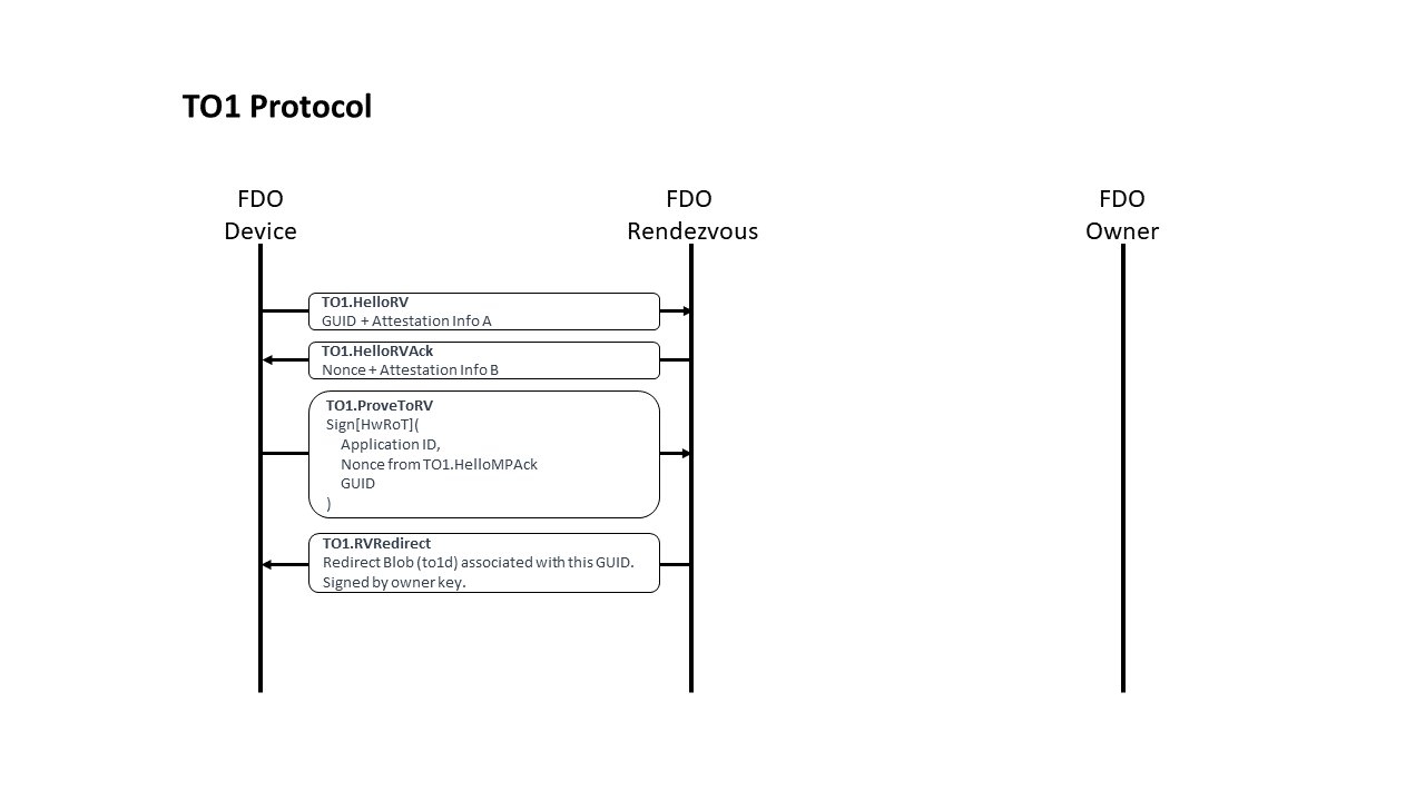
CDDL
TO1ProtocolMessages = (
    TO1.HelloRV,
    TO1.HelloRVAck,
    TO1.ProveToRV,
    TO1.RVRedirect
)
5.4.1. TO1.HelloRV, Type 30
From Device ROE to Rendezvous Server:
Message Format:
TO1.HelloRV = [
    Guid,
    eASigInfo
]
HTTP Context:
POST /fdo/100/msg/30
Message Meaning:
Establishes the presence of the device at the Rendezvous Server.
The “Guid” parameter is the GUID of the Device. This is used as an index by the Rendezvous Server to look up information associated with the Device.
If the Rendezvous Server does include a record for this Guid, processing in this protocol continues.
If the Rendezvous Server does not include a record for this Guid, then it returns an ERROR message and terminates the TO1 protocol (see error RESOURCE_NOT_FOUND; § 5.1.1.1 Error Code Values). The Device will continue to try to onboard, perhaps using a different Rendezvous Server or perhaps finding the Guid on this one at a later time, following the mandated interpretation of RendezvousInfo.
The eASigInfo variable contains signature related information, as
described in: § 3.5 Device Attestation Sub Protocol.
5.4.2. TO1.HelloRVAck, Type 31
From Rendezvous Server to Device ROE
Message Format:
TO1.HelloRVAck = [
    Nonce4,
    eBSigInfo
]
HTTP Context:
-
POST reponse, includes authorization token
Message Meaning:
Sets up Device ROE for next message.
The Nonce4 tag contains a nonce to use as a guarantee of signature freshness in
the TO1.ProveTORV.
The eBSigInfo variable contains signature related information.
5.4.3. TO1.ProveToRV, Type 32
From Device ROE to Rendezvous Server:
Message Format:
TO1.ProveToRV = EAToken
$$EATPayloadBase //= (
    EAT-NONCE: Nonce4
)
HTTP Context:
POST /fdo/100/msg/32
Message Meaning:
Proves validity of device identity to the Rendezvous Server for the Device seeking its owner, and indicates its GUID.
MAROEPrefix may be used to provide evidence of the ROE application that is running.
Nonce4 proves that the signature was just computed, and not a reply (signature ‘freshness’ test). EAT-UEID contains the FIDO Device Onboard Guid, as described in § 3.3.6 EAT Signatures.
The signature is verified using the device certificate chain contained in the Ownership Voucher.
If the device signature cannot be verified, or fails to verify, the connection is terminated with an error message (§ 5.1.1 Error - Type 255).
5.4.4. TO1.RVRedirect, Type 33
From Rendezvous Server to Device ROE:
Message Format:
The blob from the Rendezvous Server, which is: TO0.OwnerSign.to1d.
TO1.RVRedirect = to1d
HTTP Context:
-
POST reponse, with token
Message Meaning:
Indicates to the Device ROE that a new Owner is indeed waiting for it, and may
be found by connecting to any of the entries in to1dBlobPayload.RVTO2Addr containing
network address information.
-
See definition of
RVTO2Addr: § 3.3.14 RVTO2Addr (Addresses in Rendezvous 'blob') -
See additional instructions for interpreting the
RVTO2Addr: § 4.3 Transmission of Messages over the HTTP-like Protocols. -
This message is bit-for-bit identical to
TO0.OwnerSign.to1d.
After TO1.RVRedirect the TO1 protocol is complete.
5.5. Transfer Ownership Protocol 2
After the TO1 protocol is complete, the Device uses the Rendezvous 'blob' information to initiate communications with the Owner Onboarding Service in the TO2 protocol.
The TO2 Protocol is the most complicated of the protocols in FIDO Device Onboard, because it has several steps that are not present in other protocols:
-
Establishes trust in both directions: The Device uses its device attestation key and the Owner uses the Ownership Voucher.
-
Creates an encrypted channel, based on the above trust, using a supported key exchange mechanism.
-
Exchanges device service info for owner service info.
-
The Owner replaces all FIDO Device Onboard credentials in the Device (this does not include the Device’s attestation key and certificate); the Device gives the Owner an HMAC that allows it to generate a replacement Ownership Voucher. The Owner can use this new Ownership Voucher in future FIDO Device Onboard transactions (e.g., to resell the Device).
In addition, in all these operations, all unbounded data items are divided across multiple messages, to limit the size of an individual message that the Device is required to process. This causes several loops in the protocol:
-
The Ownership Voucher is transmitted header first, then entry by entry in successive messages.
-
The service info (in each direction) is transmitted in as many messages as necessary to keep the message size to a single packet. A constrained device may assume that the connection MTU size is 1500 bytes. The Owner and Device can simplify the implementation by limiting the size of each ServiceInfo message 1300 bytes, to allow room for protocol headers.
-
The Owner and Device may change the maximum ServiceInfo message the other entity may send using the fields:
TO2.DeviceServiceInfoReady.maxOwnerServiceInfoSz
and
TO2.OwnerServiceInfoReady.maxDeviceServiceInfoSz
Implementation note: A larger or smaller maximum ServiceInfo size provides a tradeoff between buffering requirements and the ability to transmit bulk data with fewer roundtrip times. As an additional tradeoff, an implementation may choose to parse CBOR bulk data incrementally to allow larger messages to be sent without needing a full message buffer.
The ServiceInfo exchange in FIDO Device Onboard allows the cooperating client entities on the Device and Owner to negotiate their own “protocol” for setting up the Device. The names and meanings of key value pairs is generally up to the Device and Owner, but examples are given above. See § 3.8 ServiceInfo and Management Service – Agent Interactions.
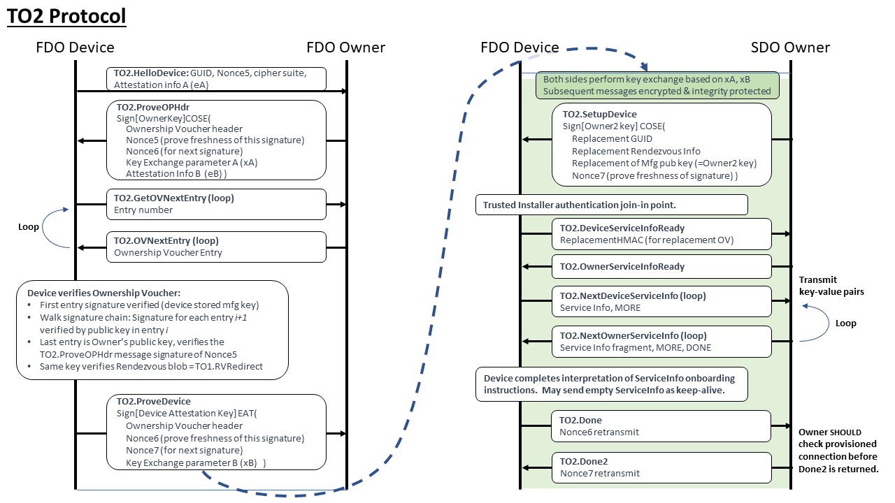
CDDL
TO2ProtocolMessages = (
    TO2.HelloDevice,
    TO2.ProveOVHdr,
    TO2.GetOVNextEntry,
    TO2.OVNextEntry,
    TO2.ProveDevice,
    TO2.SetupDevice,
    TO2.DeviceServiceInfoReady,
    TO2.OwnerServiceInfoReady,
    TO2.DeviceServiceInfo,
    TO2.OwnerServiceInfo,
    TO2.Done,
    TO2.Done2
)
5.5.1. Limitation of Round Trips
The implementation shall complete the Transfer Ownership Protocol 2 in no more than 1,000,000 round trips, overall. Owner and Device implementations should not request more iterations than this.
A given Owner implementation may limit the number of ServiceInfo iterations received from a Device, to prevent a denial of service attack.
5.5.2. TO2.HelloDevice, Type 60
From Device ROE to Owner Onboarding Service
Message Format:
TO2.HelloDevice = [
    Guid,
    Nonce5,
    kexSuiteName,
    cipherSuiteName,
    eASigInfo  ;; Device attestation signature info
]
kexSuiteName = tstr
cipherSuiteName = tstr
HTTP Context:
POST /fdo/100/msg/60
Message Meaning:
Sets up new owner for proof of ownership.
The kexSuiteName and cipherSuiteName fields indicate the key
exchange protocol and cipher suite to use. Because we assume the
Device may be constrained, it gets to choose these values; the Owner
side must support all choices that a Device can make.
The values for kexSuiteName are given in: § 3.6 Key Exchange in the TO2 Protocol
The cipher suite cipherSuiteName is as given in: § 4.4 Encrypted Message Body
The eASigInfo tag starts the Device’ signature process.
5.5.3. TO2.ProveOVHdr, Type 61
From Owner Onboarding Service to Device ROE:
Message Format:
TO2.ProveOVHdr = CoseSignature
TO2ProveOVHdrPayload = [
    OVHeader,     ;; Ownership Voucher header
    NumOVEntries, ;; number of ownership voucher entries
    HMac,         ;; Ownership Voucher "hmac" of hdr
    Nonce5,       ;; nonce from TO2.HelloDevice
    eBSigInfo,    ;; Device attestation signature info
    xAKeyExchange ;; Key exchange first step
]
NumOVEntries = uint16
TO2ProveOVHdrUnprotectedHeaders = (
    CUPHNonce:       Nonce6, ;; nonce6 is used below in TO2.ProveDevice and TO2.Done
    CUPHOwnerPubKey: PublicKey ;; Owner key, as hint
)
$COSEPayloads /= (
    TO2ProveOVHdrPayload
)
$$COSEUnprotectedHeaders /= (
    TO2ProveOVHdrUnprotectedHeaders
)
HTTP Context:
-
POST response, includes authorization token
Message Meaning:
This message serves several purposes:
-
The Owner begins sending the Ownership Voucher to the device (only the header is in this message).
-
The Owner signs the message with the Owner key (the last key in the Ownership Voucher), allowing the Device to verify (later on) that the Owner controls this private key.
-
The Owner starts the key exchange protocol by sending the initial key exchange parameter xAKeyExchange (eg., in Diffie Hellman, the parameter ‘A’) to the Device.
The Ownership Voucher’s header is sent in the OVHeader and HMac fields. The NumOVEntries value
gives the number of Ownership Voucher Entries. The Ownership Voucher entries will be sent in
subsequent messages. It is legal for this tag to have a value of zero (0),
but this is only useful in re-manufacturing situations, since the Rendezvous
Server cannot verify (or accept) these Ownership Proxies.
The HMac field is a HMAC-SHA256 or
HMAC-SHA384 over the OVHeader tag. The HMAC derives
from the Device initialization in DI.SetHMAC, or equivalent, and is based on a secret
allocated and stored in the Device.
The Device re-computes
the HMAC value against the received contents of the OVHeader tag using this stored
secret, and verifies that the HMac field has the same value. If the
values are different, the protocol ends in error.
This ensures that
the Device itself has not been reinitialized since it was originally programmed
during manufacturing.
The Owner Onboarding Service includes the hash of
device certificate chain from the Ownership Voucher (OwnershipVoucher.OVHeader.OVDevCertChain) in the
TO2.ProveOVHdr message (as OVDevCertChainHash) for the device to verify
with the HMAC. The device temporarily saves the cert chain hash on receiving the message. When
the device computes the new HMAC based on the fields received in TO2.SetupDevice
message, it uses the value of the cert chain hash that was previously
saved. The new HMAC is returned to the Owner Onboarding Service as part of TO2.Done
message.
The public key (CUPHOwnerPubKey) in the COSE unprotected field, is
the Owner Key. This key, which verifies this message’s
signature, must be compared with the public key in the last Ownership
Voucher Entry when it is received later in the sequence of this
protocol. The presence of the Owner key in this message is a
convenience for the Device (a hint), giving it the option to verify the
signature of this message immediately, then compare the given
CUPHOwnerPubKey with the later transmission.
Note that OVHeader.OVPubKey is the initial owner public key from the Ownership
Voucher Header, and should not be confused with the public key in the
unprotected header of this message.
CUPHOwnerPubKey must also be able to verify the signature of the TO1.RVRedirect
message. The Device must store the TO1.RVRedirect message (or its hash) until
the TO2.ProveOVHdr message is received. At this time, the Device can verify the
TO1.RVRedirect signature with the give Owner key in TO2.ProveOVHdr.OVPubKey. If the
TO1.RVRedirect signature does not verify, the Device must assume that a man in
the middle is monitoring its traffic, and fail TO2 immediately with an error code
message.
The eBSigInfo field continues the Device’ attestation process.
The xAKeyExchange field begins the key exchange protocol. See § 3.6 Key Exchange in the TO2 Protocol for more details on key exchange. The key exchange is finished in the TO2.ProveDevice message.
The verification of this message is critical, if complex.
The Device initially verifies this message’s COSE signature using
the supplied CUPHOwnerPubKey, then saves a copy of this key (for memory reasons, the
Device may save a suitable hash of the key). A failure in verification
causes TO2 to terminate in error.
As the Ownership Voucher entries are transmitted in successive TO2.GetOVNextEntry messages, the Device can verify them using the signature chain embedded in the Ownership Voucher, from header to entry 1 to entry 2, and so on. The last such entry signs a public key from the Owner entity that is actually driving this protocol (sometimes called the protocol server role); this is also the “Owner key”. Now the Device must verify that the Owner can sign with the Owner key’s corresponding private key. But if this public key matches the CUPHOwnerPubKey, then the signature verification at the start has verified exactly this. The Device verifies that "owner key" matches the saved public key from this message.
The device may compare public keys by comparing key material, although care must be taken to ensure the public key encodings do not cause a false failed comparison. Where feasible, the device may save the hashes computed during signature verification and repeat the verification using the Owner key from TO2.GetOVNextEntry.
The following diagram illustrates the process, using only the signature chain, for an Ownership Voucher 3 entries:
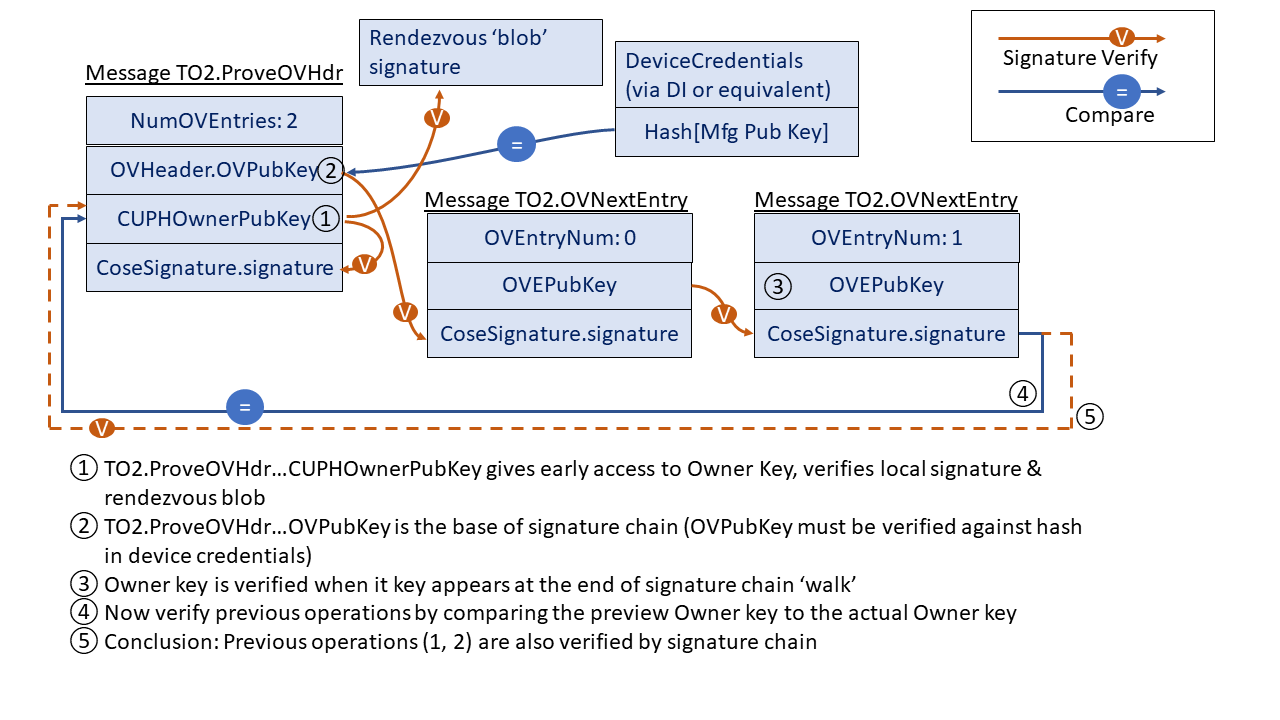
5.5.4. TO2.GetOVNextEntry, Type 62
From Device ROE to Owner Onboarding Service:
Message Format:
TO2.GetOVNextEntry = [
    OPEntryNum
]
OPEntryNum = uint8
HTTP Context:
POST /fdo/100/msg/62
Message Meaning:
Acknowledges the previous message and requests the next Ownership Voucher Entry. The integer argument, OPEntryNum, is the number of the entry, where the first entry is zero (0).
The Device MUST send successive OPEntryNum values in subsequent TO2.GetOVNextEntry.
5.5.5. TO2.OVNextEntry, Type 63
From Owner Onboarding Service to Device ROE
Message Format:
TO2.OVNextEntry = [
    OVEntryNum
    OVEntry
]
HTTP Context:
-
POST response with token
Message Meaning:
Transmits the requested Ownership Voucher entry from the Owner Onboarding Service to the Device
ROE. The value of OVEntryNum matches the value of TO2.GetOVNextEntry.OVEntryNum.
If OVEntryNum == TO2.ProveOVHdr.NumOVEntries-1, then the next state is TO2.ProveDevice. Otherwise the next state is TO2.GetOVNextEntry.
The Device ROE verifies the ownership voucher entries incrementally as follows:
Variables from OVEntryPayload:
-
HashPrevEntry– hash of previous entry. The hash of the previous entry’sOVEntryPayload. For the first entry, the hash isSHA[TO2.ProveOVHdr.OVHeader||TO2.ProveOVHdr.HMac]. -
PubKey– public key signed in previous entry (initialize withTO2.ProveOVHdr.OVHeader.OVPubKey) -
HashHdrInfo– hash of GUID and DeviceInfo, compute from TO2.ProveOVHdr as:SHA[TO2.ProveOVHdr.OVHeader.Guid||TO2.ProveOVHdr.OVHeader.DeviceInfo]-
Pad the hash text on the right with zeros to match the hash length.
-
-
For each entry:
-
Verify signature TO2.OVNextEntry.OVEntry using variable
PubKey -
Verify variable
HashHdrInfomatchesTO2.OVEntry.OVEHashHdrInfo -
Verify
HashPrevEntrymatchesSHA[TO2.OpNextEntry.OVEntry.OVEPubKey] -
Update variable
PubKeytoTO2.OVNextEntry.OVEPubKey.OVPubKey -
Update variable
HashPrevEntrytoSHA[TO2.OpNextEntryPayload] -
If
OVEntryNum == TO2.ProveOpHdr.NumOVEntries-1then verifyTO2.ProveOVHdr.pk == TO2.OVNextEntry.OVNextEntry.OVPubKey
If any verification fails, the TO2 protocol ends in error.
5.5.6. TO2.ProveDevice, Type 64
From Device ROE to Owner Onboarding Service
Message Format:
TO2.ProveDevice = EAToken
$$EATPayloadBase //= (
    EAT-NONCE: Nonce6
)
TO2ProveDevicePayload = [
    xBKeyExchange
]
$EATUnprotectedHeaders /= (
    EUPHNonce: Nonce7 ;; Nonce7 is used in TO2.SetupDevice and TO2.Done2
)
$EATPayloads /= (
    TO2ProveDevicePayload
)
HTTP Context:
POST /fdo/100/msg/64
Message Meaning:
Proves the provenance of the device to the new owner, using the entity
attestation token based on the challenge Nonce6 sent as TO2.ProveOVHdr.UnprotectedHeaders.CUPHNonce.
If the signature cannot be verified, or fails to verify, the connection is
terminated with an error message (§ 5.1.1 Error - Type 255).
Completes the key exchange, by sending xBKeyExchange in the
FIDO Device Onboard EAT payload. For more information, see section § 3.6 Key Exchange in the TO2 Protocol.
Sends Nonce7 for later use.
| Note |
|---|
| Subsequent message bodies are protected for confidentiality and integrity. |
5.5.7. TO2.SetupDevice, Type 65
From Owner Onboarding Service to Device ROE
Message Format - after decryption and verification:
;; This message replaces previous FIDO Device Onboard credentials with new ones
;; Note that this signature is signed with a new (Owner2) key
;; which is transmitted in this same message.
;; The entire message is also verified by the integrity of the
;; transmission medium.
TO2.SetupDevice = CoseSignature
TO2SetupDevicePayload = [
    RendezvousInfo, ;; RendezvousInfo replacement
    Guid,           ;; GUID replacement
    Nonce7,         ;; proves freshness of signature
    Owner2Key       ;; Replacement for Owner key
]
Owner2Key = PublicKey

$COSEPayloads /= (
    TO2SetupDevicePayload
)
HTTP Context:
-
POST response with token
Message Meaning:
This message prepares for ownership transfer, where the credentials previously used to take over the device are replaced, based on the new credentials downloaded from the Owner Onboarding Service. These credentials were: previously programmed by the DI protocol; programmed using another technique from the DI protocol; or previously updated by this message.
The changes are queued by this message, but are implemented in the Device during TO2.Done. If the TO2 protocol ends in error before TO2.Done, these changes are not implemented.
The following table indicates the transition of Ownership Credentials during TO2.Done, based on these parameters.
Table ‑. Ownership Credential Transition from TO2.SetupDevice
| DI value | Previous value | New Value | New Value (Credential Reuse) |
DI.SetCredentials. OVHeader.OVProtVer
| OwnershipCredential. OCProtVer
| unchanged | unchanged |
DI.SetCredentials. OVHeader.OVRendezvousInfo
| OwnershipCredential. OCRVInfo
| TO2SetupDevicePayload. RendezvousInfo
| unchanged |
DI.SetCredentials. OVHeader.OVGuid
| OwnershipCredential. OCGuid
| TO2SetupDevicePayload.Guid
| unchanged |
DI.SetCredentials. OVHeader.OVDeviceInfo
| OwnershipCredential. OCDeviceInfo
| unchanged | unchanged |
DI.SetCredentials. OVHeader.OVPublicKey
| hash[OwnershipCredential. OCPubKeyHash]
| TO2SetupUnprotectedHeaders. PublicKey
| unchanged |
See § 7 Credential Reuse Protocol for additional information on Credential Reuse protocol.
5.5.8. TO2.DeviceServiceInfoReady, Type 66
From Device ROE to Owner Onboarding Service
Message Format - after decryption and verification:
TO2.DeviceServiceInfoReady = [
    ReplacementHMac, ;; Replacement for DI.SetHMac.HMac or equivalent
    maxOwnerServiceInfoSz    ;; maximum size service info that Device can receive
]
;; A null HMAC indicates acceptance of credential reuse protocol
ReplacementHMac = HMac / null
maxOwnerServiceInfoSz = uint / null
HTTP Context
POST /fdo/100/msg/66
Message Meaning:
This message signals a state change between the authentication phase of the protocol and the provisioning phase (ServiceInfo) negotiation.
The ReplacementHMac variable completes the information needed in the Owner Onboarding Service to create a new Ownership Voucher for the Device.
The field maxOwnerServiceInfoSz, if non-null, indicates the maximum size Owner ServiceInfo message that the Device is able to process from the Owner. This may indicate a decrease or increase in size from the recommended ServiceInfo limit of 1300 bytes per message. It is up to the Device to ensure that it can receive this message via the underlying transport mechanism. A null value of maxOwnerServiceInfoSz indicates the recommended maximum ServiceInfo size, as above.
If the Device supports Credential Reuse protocol and all the conditions for Credential Reuse are satisfied in TO2.SetupDevice, then it can return ReplacementHMac as CBOR null. See § 7 Credential Reuse Protocol for additional information on Credential Reuse protocol.
If ReplacementHMac is an HMac (i.e., non-null) ReplacementHMac may be used by the Owner to create a replacement Ownership Voucher for the device. This permits FIDO Device Onboard to onboard the device again at a future date.
If the Device returns a non-null ReplacementHMac, the Owner MUST either create a new Ownership Voucher, or accept that the Device will not be able to onboard using FIDO Device Onboard again.
Even if ReplacementHMac is non-null (i.e., a valid HMac), the Device MAY refuse to support resale at a later time. In this case, it is recommended that an out-of-band mechanism be provided to let the Owner know that the resale protocol credentials will no longer work. The details of such a mechanism are outside the scope of this document.
The TO2.DeviceServiceInfoReady and TO2.OwnerServiceInfo messages are the joining point for the Untrusted Installer and Trusted Installer authentication options.
The Trusted Installer authentication option is not currently defined in FIDO Device Onboard.
5.5.9. TO2.OwnerServiceInfoReady, Type 67
From Owner Onboarding Service to Device ROE
Message Format - after decryption and verification:
TO2.OwnerServiceInfoReady  = [
    maxDeviceServiceInfoSz    ;; maximum size service info that Owner can receive
] ;; empty array
maxOwnerServiceInfoSz = uint / null
HTTP Context:
-
POST response with token
Message Meaning:
This message responds to TO2.DeviceServiceInfoReady and indicates that the Owner Onboarding Service is ready to start ServiceInfo.
The field maxDeviceServiceInfoSz, if non-null, indicates the maximum size Device ServiceInfo message that the Owner is able to process from the Device. This may indicate a decrease or increase in size from the recommended ServiceInfo limit of 1300 bytes per message. It is up to the Owner to ensure that it can receive this message via the underlying transport mechanism. A null value of maxDeviceServiceInfoSz indicates the recommended maximum ServiceInfo size, as above.
5.5.10. TO2.DeviceServiceInfo, Type 68
From Device ROE to Owner Onboarding Service
Message Format - after decryption and verification:
TO2.DeviceServiceInfo = [
    IsMoreServiceInfo,   ;; more ServiceInfo to come
    ServiceInfo          ;; service info entries
]
IsMoreServiceInfo = bool
HTTP Context
POST /fdo/100/msg/68
Message Meaning:
Sends as many Device to Owner ServiceInfo entries as will conveniently fit into a message, based on protocol and Device constraints. This message is part of a loop with TO2.OwnerServiceInfo.
On the first ServiceInfo message, the Device must include the devmod module messages.
The IsMoreServiceInfo indicates whether the Device has more
ServiceInfo to send. If this flag is True, then the subsequent
TO2.OwnerServiceInfo message MUST be empty, allowing the Device to
send additional ServiceInfo items.
If the previous TO2.OwnerServiceInfo.IsMoreServiceInfo had value True,
then this message MUST contain:
-
IsMoreServiceInfo= False -
ServiceInfois an empty array
This permits the Owner to send arbitrary sized collections of ServiceInfo.
All individual ServiceInfo items must fit into a single message.
The size of TO2.DeviceServiceInfo is limited to TO2.OwnerServiceInfoReady.maxDeviceServiceInfoSz, if non-null.
Otherwise, it is limited based on an MTU size of 1500 bytes. A limit
of 1300 bytes may be used as a rule of thumb in this case.
5.5.11. TO2.OwnerServiceInfo, Type 69
From Owner Onboarding Service to Device ROE
Message Format - after decryption and verification:
TO2.OwnerServiceInfo = [
    IsMoreServiceInfo,
    IsDone,
    ServiceInfo
]
IsDone = bool
HTTP Context:
-
POST response with token
Message Meaning:
Sends as many Owner to Device ServiceInfo entries as will conveniently fit into a message, based on protocol and implementation constraints. This message is part of a loop with TO2.DeviceServiceInfo.
If the IsMoreServiceInfo was True on the previous TO2.DeviceServiceInfo message, this message MUST have:
-
IsMoreServiceInfo= False -
IsDone= False -
ServiceInfois an empty array
This permits the Device to send arbitrary sized collections of ServiceInfo.
When the Owner has no more ServiceInfo to send, it can terminate the ServiceInfo process by setting IsDone=True. Once IsDone=True is set, all subsequent ServiceInfo messages must contain:
-
IsDone=True (for Owner ServiceInfo messages)
-
IsMoreServiceInfo = False (for Device and Owner ServiceInfo messages)
-
ServiceInfo is an empty array (for Device and Owner ServiceInfo messages)
The Device MAY send additional (empty) TO2.DeviceServiceInfo messages to the Owner as a keepalive mechanism [RFC1122]. This is intended to allow the Device to perform lengthy computation between the end of ServiceInfo and the TO2.Done message without the Owner side timing out and declaring a failure.
A Device SHOULD send such keepalive messages if the interval between the first message containing IsDone=True and the TO2.Done message involves processing of long or unknown interval. A suggested keepalive interval for this phase of TO2 is 60 seconds.
All individual ServiceInfo items must fit into a single message.
The size of TO2.OwnerServiceInfo is limited to TO2.DeviceServiceInfoReady.maxOwnerServiceInfoSz, if non-null.
Otherwise, it is limited based on the MTU size of 1500 bytes. A limit
of 1300 bytes may be used as a rule of thumb in this case.
5.5.12. TO2.Done, Type 70
From Device ROE to Owner Onboarding Service:
Message Format - after decryption and verification:
TO2.Done = [
    Nonce6         ;; Nonce generated by Owner Onboarding Service
                   ;; ...and sent to Device ROE in Msg TO2.ProveOVHdr
]
HTTP Context:
POST /fdo/100/msg/70
Message Meaning:
Indicates successful completion of the Transfer of Ownership.
The Client and Owner software now transitions to completing the requested actions between Device and Owner.
The Owner may use this information to construct a new Ownership Voucher based on the Owner2 key and the new information configured into the Device in the TO2.SetupDevice message. This information permits the Owner to effect a new transfer of ownership by re-enabling the FIDO Device Onboard software on the Device. The mechanism to re-enable FIDO Device Onboard software on a given Device is outside the scope of this document.
The credentials received into the Device during the TO2.SetupDevice are implemented to replace the DeviceCredentials at this time.
5.5.13. TO2.Done2, Type 71
From Owner Onboarding Service to Device ROE:
Message Format - after decryption and verification:
TO2.Done2 = [
    Nonce7
]
HTTP Context:
-
POST response with token
Message Meaning:
This message provides an opportunity for a final ACK after the Owner has invoked the System Info block to establish agent-to-server communications between the Device and its final Owner.
When possible, the TO2.Done2 should be delayed until the Device has established agent-to-server communications, allowing a FIDO Device Onboard error to occur when such communications fail.
On some constrained devices, FIDO Device Onboard software might not be able to run after the agent-to-server communications are set up. On these systems, this ACK can happen right after the TO2.Done message. Such systems cannot recover from a failure that appears after FIDO Device Onboard has finished, but that prevents agent-to-server communications from being established.
Examples of systems that cannot generate a response after agent-to-server communications are working include:
-
Constrained systems that don’t have enough resources to run both FIDO Device Onboard and the agent-to-server subsystems.
-
Systems that require a reboot to complete agent-to-server setup.
5.6. After Transfer Ownership Protocol Success
The following are useful steps that SHOULD be performed at this time. Since Devices vary, Device owners may have to perform some of these steps earlier or later.
-
The Owner Onboarding Service transfers all device information to the manager server.
-
The Device ROE may indicates to its OS-level handler to invoke the Device to Manager Agent for the manager service. This Device to Manager Agent should be given all the information that the ROE has now collected.
-
The Device ROE transitions to the IDLE state.
-
The new Owner has changed all credentials in the device, except the Device key (e.g., hardware root of trust) and OCDeviceInfo, and has sufficient information to construct an Ownership Voucher with zero entries.
6. Resale Protocol
After the transfer of ownership completes (i.e., the TO2 Protocol finishes), the
Device switches an internal state variable to inhibit the
device’s software from running FIDO Device Onboard, such as is described
for DeviceCredential.DCActive (See § 3.4.1 Device Credential Persisted Type (non-normative)).
A device implementation might also stop a thread or process from running to achieve the same effect, perhaps freeing resources for Device operation. In the case of a MCU-based implementation, the FIDO Device Onboard code might only be able to run when external software calls a specific entry point for it.
The Owner may use System or OS level commands to re-enable FIDO Device Onboard for a new
transfer of Ownership. How this is accomplished is outside the scope
of this document. In some systems, it may involve setting the DeviceCredential.DCActive flag to True, but other system-dependent
changes may be needed.
In the TO2 Protocol, the FIDO Device Onboard software in the Device ROE stores new
credentials that are only known to the Owner. How the device info is updated is
described in the context of the TO2.SetupDevice message. Please note that the public
key stored in the device is updated to the Owner2 key, a key that is separate
from the Owner key in the original Ownership Voucher. This is to
prevent this key from being used to correlate the original Ownership Voucher from the one being generated for
resale in the TO2 Protocol.
However, Correlation of Ownership Vouchers using the Device certificate is still possible for some Device attestation key types.
Subsequently, in the [TO2.Done] message, the Device transfers to the Owner the HMAC of the stored device credentials. This HMAC is used by the Owner exactly as the HMAC supplied to the ODM in the DI.SetHMAC message is used, to create a new Ownership Voucher.
Resale, then, involves the following conceptual steps whose details are device and site dependent, and thus are mostly outside the scope of this document:
-
The current Owner obtains a public key from the target Owner. The Owner retrieves the replacement Ownership Voucher from the latest run of the TO2 protocol, and extends it to the target Owner’s public key.
-
The Device is reconditioned to remove all run-time changes and brought back to a factory state. This includes removing any secrets, except for the FIDO Device Onboard credentials from the TO2 Protocol.
-
The Device is set to enable to FIDO Device Onboard Device software to run.
-
The Device is powered down, shipped, and re-installed in its new location.
-
The target Owner accepts the Ownership Voucher and enables itself as a FDO Owner. The target Owner implements the TO0 protocol
-
The device onboards to the target Owner. Yet a new Ownership Voucher is created.
It may be that, when resale time comes, the Owner wishes to change the rendezvous information that is stored in the Device ROE. This may be accomplished by performing a transfer of ownership (using the TO2 Protocol) from the Owner to itself, allowing replacement of the credentials in the TO2.SetupDevice message.
6.1. FIDO Device Onboard Devices that Do Not Support Resale
A device may, at its option, implement only a limited number of FIDO Device Onboard transfers of ownership. There are various reasons for this:
-
Each transfer might consume some OTP memory or other resource, and the total amount is limited.
-
A device is intended to be discarded after its first Ownership Transfer.
-
The ability to use FIDO Device Onboard again on a Device might be thought of as an attack vector to disable or even steal the device.
-
An Owner may be concerned that the Device’s key could be correlated to its previous onboarded location, giving an attacker more information about the Device.
In this case, the Owner’s Device Management Service must disable all FIDO Device Onboard credentials and software after the initial transfer of ownership succeeds. The TO2 protocol parameters can be used to disable the FIDO Device Onboard credentials.
A device may also indicate to the Owner that it can no longer perform FIDO Device Onboard by setting TO2.DeviceServiceInfoReady.ReplacementHMAC to CBOR null.
6.2. FIDO Device Onboard Owner that Does Not Support Resale
An Owner may elect not to support the resale capability, even if the underlying Device is capable of doing so. The Owner is still required to provide new credentials for the Device in the TO2.SetupDevice message. The Owner should then discard the credentials in a manner that will ensure that neither the Owner itself nor any malicious party can ever obtain them. This involves:
-
The Owner must ensure the security of the Owner2 private key such as discarding the key.
-
The Owner must delete the HMAC received from the Device.
-
The Owner must not extend and distribute the replacement Ownership Voucher, created during the TO2 protocol, before deciding to discard the key or HMAC.
7. Credential Reuse Protocol
Credential Reuse protocol allows devices to reuse the Device Credentials across multiple onboardings. The intended use case for this protocol is to support demos and testing scenarios where the onboarding can be run repeatedly and quickly without having to change the Ownership Voucher or resetting the system after each onboarding. Since credential reuse can permit the previous Owner unlimited access to the device, it is NOT recommended for use in the normal device supply chain.
Credential reuse is selected by the Owner, and accepted or rejected by the device.
A Device implementation may elect to disable credential reuse as a security measure, either directly in the firmware, or using a write-once flag in the hardware.
In normal credential use, the Owner changes the Device Credential in TO2.SetupDevice, which also creates a new Ownership Voucher. At the end of a successful TO2 protocol, the device deactivates FIDO Device Onboard. If the Owner re-enables FIDO Device Onboard, the next onboarding uses the new Ownership Voucher.
For credential reuse, the TO2 protocol supports a special case which indicates to the device not to change the Device Credential in TO2.SetupDevice. The device still runs the complete TO2 protocol to the end but does not deactivate FIDO Device Onboard at the end of the protocol.
The Credential Reuse protocol is as follows:
In TO2.SetupDevice:
-
If
TO2.SetupDevice.Guid==TO2.ProveOVHdr.OVHeader.OVGuid(GUID same as previous),
and
TO2.SetupDevice.RendezvousInfo==TO2.ProveOVHdr.OVHeader.OVRendezvousInfo(RendezvousInfo same as previous)
and
TO2.SetupDevice.Owner2Key== Owner’s current public key (which is the public key in the last entry of Ownership Voucher),
and TO2.SetupDevice is verified as a valid COSE signature primitive
and the device supports the credential reuse protocol
-
Then
-
Device does not update the Device Credential,
-
and Device does not internally change the HMAC,
-
and in TO2.DeviceServiceInfoReady message, devices responds with TO2.DeviceServiceInfoReady.ReplacementHMac equal to CBOR null.
-
If the Device does not support the credential reuse protocol, but all other conditions are met, the Device causes a protocol error, and sends an error message CRED_REUSE_ERROR, which terminates the TO2 protocol.
Subsequently, the Device restarts running FIDO Device Onboard as for any other failure.
Appendix B: Device Key Provisioning with ECDSA
The following procedure is used to initialize the FIDO Device Onboard Device key and certificate, before the FIDO Device Onboard Device Initialize (DI) protocol is run. This is presented as an example, and is non-normative.
-
An ECDSA key pair is generated, and a Certificate Signing Request (CSR) is signed with the new private key.
-
The recommended way to do this is to generate the ECDSA key pair and the signed CSR inside the FIDO Device Onboard device.
-
If an appropriate security level is possible in device manufacture, it is acceptable for the manufacturer to generate the key pair outside the FIDO Device Onboard Device, generate its own CSR, program the FIDO Device Onboard Device with the private key, then discard its copy of the ECDSA private key.
-
-
The CSR is submitted to a Certificate Authority trusted by the device manufacturer to create a Device certificate and certificate chain.
-
The device certificate should not expire unless the device manufacturer has a reason for FIDO Device Onboard to be performed before a certain date. One such reason is recent discussion about the potential for quantum computers in the future.
-
-
The Device private key is stored with Confidentiality, Availability, and Integrity (CAI) protection in the Device ROE that is performing FIDO Device Onboard.
-
The certificate chain is attached to the Ownership Voucher, as described in section § 2.7 The Ownership Voucher.
The Ownership Voucher HMAC, passed in the DI protocol, references the initial Device Certificate. This means that the ECDSA key and certificate must be programmed before the Device Initialize protocol is run. The Manufacturer is trusted to match the Device certificate information to the required DI protocol fields. Subsequent to this, the Ownership Voucher HMAC (OwnershipVoucher.hmac) is used to detect if the Device Certificate is changed in the supply chain.
Appendix C: FIDO Device Onboard 1.1 Cryptographic Summary
The following table summarizes cryptography usage within FIDO Device Onboard. Different cryptographic options are given, where appropriate.
This section is non-normative
.| Category | FIDO Device Onboard usage |
| Device HMAC |
HMAC-SHA256 with HMAC secret (DCHmacSecret) of 128 bits HMAC-SHA384 with HMAC secret (DCHmacSecret) of 512 bits |
| Hash of Owner Key | SHA256 SHA384 or the device may store complete Owner public key |
| Ownership Voucher (Owner attestation) |
RSA2048RESTR, RSA2048 or RSA3072
RSA2048RESTR is intended for legacy hardware |
| Ownership Voucher (Owner attestation) | SECP256R1 SECP384R1 |
| Ownership Voucher | SHA256 SHA384 |
| Device attestation, DAA | Intel® EPID: EPID1.0, 1.1, 2.0 |
| Device attestation ECDSA | secp256r1 (with SHA256 hash) secp384r1 (with SHA384 hash) |
| Key Exchange, DH |
DHKEXid14 (2048-bit modulus) owner and client randoms are 256 bits each
DHKEXid15 (3072 bit modulus) owner and client randoms are 768 bits each |
| Key Exchange, Asymmetric |
RSA2048RESTR RSA-OAEP-MGF-SHA256 Device, Owner Random of 256 bits
RSA_UR, 3072 bits RSA-OAEP-MGF-SHA256 Device, Owner Random of 768 bits SHA256 may be used as mask generation function for RSA-OAEP. However, larger Device and Owner Randoms required for SVK, SEK. Targeted to legacy hardware; use DHKEXid14 or id15 where possible. |
| Key Exchange, ECDH |
secp256r1 or secp384r1, keys used once only, Device, Owner random of 128 bits
secp384r1, keys used once only Device, Owner random of 384 bits Larger Device and Owner Randoms required for SVK, SEK. |
| Key Exchange, ECDH, for legacy devices |
secp256r1, keys used once only. Device, Owner random of 128 bits
secp256r1, keys used once only. Device, Owner random of 512 bits |
| Key Derivation Function |
SHA256 based SEK, SVK entropy is 128 bits (SVK 256 bits, but with lower entropy)
SHA384 based SEK is 256 bits SVK is 512 bits SEVK = SEK || SVK |
| SEK (Session Encryption Key) | 128 bits 256 bits |
| SVK (Session Verification Key) | 256 bits, with 128 bits entropy 512 bits |
| TO2 Session HMAC |
HMAC-SHA256 HMAC-SHA384 HMAC-SHA384 state is 512 bits. |
| TO2 Session Encryption, counter mode |
AES-128/CTR IV 16 bytes, Counter is low 4 bytes of IV.
AES-256/CTR IV is 16 bytes, Counter is 4 bytes of IV. Session limits on TO2 protocol prevent counter wrap |
| TO2 Session Encryption, CBC mode |
AES-128/CBC IV is 16 bytes
AES-256/CBC IV is 16 bytes Invalid CBC causes entire connection to fail. this mitigates padding attack |
| TO2 Protocol Roundtrip Limit | 1M (1e6) rounds |
Appendix D: Intel® Enhanced Privacy ID (Intel® EPID) Considerations
As Intel® has acted to enable other companies to use Intel® EPID 2 for a variety of devices and applications, a new Intel® EPID 2 attributes feature has been added by the Intel® Key Generation Facility (iKGF), an independent key issuing authority. Intel® EPID attributes are identifiers associated with an Intel® EPID group, and reflected in the group certificate. A common set of attributes is also represented in the 128-bit Intel® EPID 2 Group ID.
Group ID attributes are important because Intel® EPID does not identify a device except as the member of a group. Thus, an Intel® EPID signature is only as trustworthy as the least trustworthy member of the group, implying that—for best results—all members of the group should be equally trustworthy.
The group ID attribute allows an Intel® EPID user to work with Intel® Key Generation Facility (iKGF) so that all devices in a given Intel® EPID group have the same security posture (e.g., the same binary or the same source code base). The iKGF can work with the device builder to allocate multiple Intel® EPID groups from within a single “group address space” so that a given product type can be detected by a 128-bit mask-and-compare operation.
The Owner is responsible for maintaining a list of Intel® EPID attribute mask-and-compare sets for each kind of device that it is provisioning. When an Intel® EPID signature appears at the Owner (in the TO2 Protocol):
-
The Group ID is compared against the Intel® EPID Attribute mask-and-compare sets to determine that this device is supported by this Owner (if not, the signature is rejected)
-
The Group is checked for revocation (if so, the signature is rejected)
-
The signature is verified against the group public key (if it fails to verify, the signature is rejected)
We envision that Intel® EPID attribute mask-and-compare sets are included by manufacturers as part of their product documentation.
Intel® Enhanced Privacy ID (Intel® EPID) 1.0 Signatures (type EPID10)
Intel® EPID 1.0 signature information is encoded using the EPID10 signature type, using the “eA”, “eB” and “eSig” fields, each from separate messages. The contents of each field is as follows:
-
eA encodes the Intel® EPID group ID as 4 bytes, in network byte order (MSB first):
Table ‑. eA Encoding, type EPID10
| Type | Name | Description |
|---|---|---|
| BYTE[4] | groupId | Intel® EPID 1.0 group ID |
-
eB encodes the Intel® EPID certificate and other items. The SIGRL is inside the group certificate. Length values (UInt16) are encoded in network order (MSB first):
Table ‑. eB Encoding, type EPID10
| Type | Name | Description |
|---|---|---|
| UInt16 | groupCertSigma10Size | Size of data in groupCertSigma10 field |
| BYTE[] | groupCertSigma10 | Legacy group certificate (binary format) |
-
eSig encodes the signature, according to the Intel® EPID 1.0 specification. The length is given in the message format:
Table ‑. eSig Encoding, type EPID10
| Type | Name | Description |
|---|---|---|
| BYTE[] | Signature | Intel® EPID 1.0 signature according to Intel® EPID 1.0 specification |
The data being signed is:
Table ‑. Data Signatures, type EPID10
| Type | Name | Description |
|---|---|---|
| BYTE | ID-length | Length of ID field |
| BYTE[] | ID | MAROEPrefix, same as in the EAT token |
| BYTE[16] | Nonce | Nonce value same as in message body (“n4” tag in messages: TO1.ProveToRV and “n6” tag in TO2.ProveDevice) |
| BYTE[] | Message body | As in this protocol specification, from open to close brace bracket of JSON text. |
Intel® Enhanced Privacy ID (Intel® EPID) 1.1 Signatures (type EPID11)
Intel® EPID 1.1 signature information is encoded using the EPID11 signature type, using the “eA”, “eB” and “eSig” fields, each from separate messages. The contents of each field is as follows:
-
eA encodes the Intel® EPID group ID as 4 bytes, in network byte order (MSB first):
Table ‑. eA Encoding, type EPID11
| Type | Name | Description |
|---|---|---|
| BYTE[4] | groupId | Intel® EPID 1.1 group ID |
-
eB encodes the Intel® EPID certificate and other items. The SIGRL is inside the group certificate. Length values (UInt16) are encoded in network order (MSB first):
Table ‑. eB Encoding, type EPID11
| Type | Name | Description |
|---|---|---|
| UInt16 | groupCertSigma10Size | Size of data in groupCertSigma10 field |
| BYTE[] | groupCertSigma10 | Legacy group certificate (binary format) |
| UInt16 | groupCertSigma11Size | Size of data in groupCertSigma11 field |
| BYTE[] | groupCertSigma11 | X.509 group certificate |
| UInt16 | sigRLSize | Size of data in sigRL field (in bytes) |
| BYTE[] | sigRL | SigRL as given below |
-
If there is no SIGRL, sigRLSize is zero, and sigRL is empty (not present).
-
sigRL non-zero implies that n2 > 0 (below).
The sigRL format is as follows (all fields are encoded in network order (MSB first)):
Table ‑. SigRL Format
| Type | Field Name | Description |
|---|---|---|
| UInt16 | sver | Intel® EPID version number. Must be 0x0001 for Intel® EPID1.1 |
| UInt16 | blobID | ID of the data type. Must be 0x000e for SigRL |
| UInt32 | gid | Group ID |
| UInt32 | RLver | Revocation list version number |
| UInt32 | n2 | Number of entries in SigRL |
| BYTE[64] (n2 of them) | B[i] for i in range [0; n2-1] | Bi elements of G3 |
| BYTE[64] (n2 of them) | K[i] for i in range [0; n2-1] | Ki elements of G3 |
| BYTE[64] | sig | 512-bit ECDSA signature on the revocation list signed by the key issuer |
-
eSig encodes the signature, according to the Intel® EPID 1.1 specification. The length is given in the message format:
Table ‑. eSig Encoding, type EPID11
| Type | Name | Description |
|---|---|---|
| BYTE[] | signature | Intel® EPID 1.1 signature according to the Intel® EPID 1.1 specification |
The data being signed is:
Table ‑. Data Signatures, type EPID11
| Type | Name | Description |
|---|---|---|
| BYTE[48] | Prefix | All zeros, except: Prefix[4]=0x48 and Prefix[8]=0x8 |
| BYTE[16] | ID | MAROEPrefix, same as in message body |
| BYTE[16] | Zero-padding | Zeros |
| BYTE[16] | Nonce | Nonce value same as in message body (“n4” tag in messages: TO1.ProveToRV and “n6” tag in TO2.ProveDevice) |
| BYTE[16] | Zero-padding | Zeros (used to allow Nonce to be 32 bytes) |
| BYTE[] | Message body | As in this protocol specification, from open to close brace bracket of JSON text. |
Intel® Enhanced Privacy ID (Intel® EPID) 2.0 Signatures (type EPID20)
Intel® EPID 2.0 signatures are encoded using “eA”, “eB” and the “eSig” fields, each from separate messages. The contents of each field is as follows:
-
eA encodes the Intel® EPID group ID as 16 bytes, in network byte order (MSB first). Devices which use Intel® EPID 2.0 with 32-bit group IDs must zero pad the top 96 bits.
Table ‑. eA Encoding, type EPID20
| Type | Name | Description |
|---|---|---|
| BYTE[16] | groupId | Intel® EPID 2.0 group ID |
-
eB encodes the signature revocation list (sigRL) and Intel® EPID group public key. Length values (UInt16) are encoded in network order (MSB first):
Table ‑. eB Encoding, type EPID20
| Type | Name | Description |
|---|---|---|
| UInt16 | sigRLSize | Size of data in sigRL field |
| BYTE[sigRLSize] | sigRL | SigRL according to Intel® EPID 2.0 specification |
| UInt16 | publicKeySize | Size of data in publicKey field |
| BYTE[publicKeySize] | publicKey | Group public key according to Intel® EPID 2.0 specification |
-
eSig encodes the signature, according to the Intel® EPID 2.0 specification. The length is given in the message format.
Table ‑. eSig Encoding, type EPID20
n| Type | Name | Description |
|---|---|---|
| BYTE[] | signature | Intel® EPID 2.0 signature according to Intel® EPID 2.0 specification |
Appendix E: IANA Considerations
Locally Defined Numbers
The following numbers are chosen from the "Reserved for Private Use" space of the IANA repository: COSE Header Parameters:
CUPHNonce =-17760701 CUPHOwnerPubKey=-17760702
The following numbers are chosen from the "Reserved for Private Use" space of the IANA repository: COSE Algorithms.
COSEAES128 CBC =-17760703 COSEAES128 CTR =-17760704 COSEAES256 CBC =-17760705 COSEAES256 CTR =-17760706
The following numbers are chosen from the "Reserved for Private Use" space of the repository for Entity Attestation Token, which we believe will be created within IANA:
EAT-FDO =-17760707 EATMAROEPrefix =-17760708 EUPHNonce =-17760709