Status of This Document
This section describes the status of this document at the time of its publication. Other documents may supersede this document. A list of current FIDO Alliance publications and the latest revision of this technical report can be found in the FIDO Alliance specifications index at https://fidoalliance.org/specifications/.
This document was published by the FIDO Alliance as a Working Draft Specification.
If you wish to make comments regarding this document, please Contact Us.
All comments are welcome.
This is a Working Draft Specification and is not intended to be a basis for any implementations as the Specification may change. This document is merely a FIDO Alliance working group internal and member-confidential document. It has no official standing of any kind and does not represent consensus of the FIDO Alliance. No rights are granted to prepare derivative works of this Specification. Entities seeking permission to reproduce portions of this Specification for other uses must contact the FIDO Alliance to determine whether an appropriate license for such use is available.
Implementation of certain elements of this Specification may require licenses under third party intellectual property rights, including without limitation, patent rights. The FIDO Alliance, Inc. and its Members and any other contributors to the Specification are not, and shall not be held, responsible in any manner for identifying or failing to identify any or all such third party intellectual property rights.
THIS FIDO ALLIANCE SPECIFICATION IS PROVIDED “AS IS” AND WITHOUT ANY WARRANTY OF ANY KIND, INCLUDING, WITHOUT LIMITATION, ANY EXPRESS OR IMPLIED WARRANTY OF NON-INFRINGEMENT, MERCHANTABILITY OR FITNESS FOR A PARTICULAR PURPOSE.
Note: For certification, requirements outside this specification might apply. Those seeking FDO certification can refer to the applicable certification documentation for additional information and requirements.
1. Introduction
1.1. Scope
1.1.1. Key Words
The keywords “MUST,” “MUST NOT,” “REQUIRED,” “SHALL,” “SHALL NOT,” “SHOULD,” “SHOULD NOT,” “RECOMMENDED,” “MAY,” and “OPTIONAL” in this document normative statements are to be interpreted as described in BCP 14, RFC2119, RFC8174 when, and only when, they appear in all capitals (aka. upper case), as shown here.
1.1.2. Statement Type
Please note a very important distinction between different sections of text throughout this document. There are two distinctive kinds of text: informative comment and normative statements.
Whether unlabeled or labeled as normative, text is assumed to be normative. Some definitions are explicitly labeled as non-normative.
Figures and diagrams are non-normative unless explicitly labeled in the caption or the document text as normative.
References to domain names in the text: name.fidoalliance.org are examples. These are not intended to refer to actual domain names or services. The domain name used is intended to avoid overlapping a domain name that might be assigned now or in the future.
Purely informative comments, which are always non-normative, are labeled as follows:
This is the second paragraph of text of the kind informative comment ...
This is the nth paragraph of text of the kind informative comment ...
1.2. Terms and Definitions
See protocol entities definitions in: § 2.3 Protocol Entities
Refer to the FIDO Glossary [FIDOGlossary] document.
1.2.1. FIDO Glossary Extension
The following terms extend the FIDO glossary to cover this document:
- attestation
-
In this document: Device Attestation or Owner Attestation
- device attestation
-
attestation from the Device to the Rendezvous Server or from the Device to the Owner, based on Entity Attestation Token [EAT]
- owner attestation
-
Owner signature in
TO0.OwnerSignandTO2.ProveOVHdr20that authenticates the Owner as owning the key at the end of the OVEntries list (the "Owner key"). - authentication (of non-human entities)
-
The proof of a claim of identity from one entity to another.
- {HTTP, TLS} authentication
-
the phase of the specified protocol by which protocol entities prove their identity to each other; the process by which this is achieved.
- {client, server} authentication
-
the process or phase of a protocol by which the given entity proves its identity
- (TO2 protocol) authentication phase
-
The portion of TO2 messages that perform authentication of Owner and Device to each other. In this specification, the authentication phase extends from the start of the protocol until the TO2.SetupDevice20 message.
- (HTTP) authentication token
-
A token carried in a HTTP session to link it to other HTTP sessions.
- (protocol name) client
-
The entity of the named protocol that initiates the connection (i.e., it sends the first message or packet). See "server."
- (protocol name) server:
-
The entity of the named protocol that receives the connection (i.e., it receives the first message orpacket). See "client."
- token:
-
By context, either an Entity Attestation Token ([EAT]) or an HTTP token, transmitted in the HTTP "Authorization" header (see § 4.3 Transmission of Messages over the HTTP-like Protocols).
- device onboarding:
-
Device onboarding is the process of installing secrets and configuration data into a device so that the device is able to connect and interact securely with an IoT platform or other suitable Computing Platform
- uint8, uint16, uint32
-
In this document, these refer to CBOR datatypes which are defined in this document (section § 3.2 Base Types). The data types are compatible with those of the same name in the FIDO Glossary, but the reader must also take into account CBOR semantics,such as for legal encodings. Note that the CDDL versions are lowercase, and the FIDO glossary uses upper case.
- bitwise concatenation
-
Bitwise concatenation, denoted by double vertical bar (a || b), is a binary operation on values a and b that yields a value c whose length is len(a) + len(b) and whose value is all the bits in a followed by all the bits in b. Example a is 6 bits 0x2a and b is 4 bits 0xb, then a||b = 0x2ab.
- user
-
A human user, with the context specified in the text.
- EPID
-
Intel® Enhanced Privacy ID, a security technology for anonymous group attestation. EPID was supported in previous versions of FIDO Device Onboard, up to version 1.1. EPID is not supported in this version (2.0). Some protocol definitions for EPID are maintained in this document. They are marked as legacy definitions.
- IoT Platform
-
A computing platform or server that runs supporting software to control remote IoT devices.
- Computing Platform
-
A server that provides any software services to remote devices. Examples of such services: security services (authentication and others), applications access or download, data/database access, storage for data collection or archiving, integration or coordination between devices.
- IoT or Computing Platform
-
Either an IoT platform or a Computing Platform.
- Late Binding
-
In device onboarding, waiting until a device is deployed and being installed before a binding is established between the device and its controlling computing platform. This term is by analogy to dynamic binding of variables in some programming languages.
1.2.2. FIDO Device Onboard Specific Definitions
- Delegate (a.k.a. "Delegate Owner", "Delegated Owner" or "Owner’s Delegate")
-
An Onboarding Service which is not in possession of the Owner Key, and therefore must present a Delegate Certificate to prove itself authorized to act on the behalf of Owner.
- Delegate Protocol
-
The additional protocol interactions that permit Delegation. See section § 3.5.2 Delegate Mechanism ("Delegation").
- Delegation
-
An (operational) processes by which an Owner can delegate authority another server (the Delegate Owner), allowing the Delegate Owner to onboard on behalf of the Owner. The Delegate Owner uses a Delegate Certificate to authorize this function.
- Delegate Owner
-
A subsidiary FDO Owner site that has been delegated permission to onboard on behalf of an Owner. The site uses a Delegate Certificate issued by this Owner to authorize the onboarding.
- Delegate Certificate
-
An X.509 Certificate which authorizes a Delegate to onboard on behalf of its issuer (the Owner). The Delegate Certificate references a public key owned by the Delegate and is signed by the Owner as an authorization. A Delegate Certificate can be an isolated X.509 certificate or can include a certificate chain (x5chain).
- Delegate Chain
-
A certificate chain (X5CHAIN) which authorizes a Delegate. This chain is rooted by the Owner Key, and terminates with the Delegate Key.
- Delegate Key
-
A Private Key held by a Delegate Onboarding Service that identifies it within FDO protocols. A Delegate Certificate must include the Delegate public key as authorization.
- Device
-
The device being onboarded with this protocol,usually assumed to be an headless device. The device often hosts a protocol entity, also called Device. By convention in this document, we capitalize the protocol entity.
- Device Credential
-
set of credentials stored in the device at manufacture. See § 3.4.1 Device Credential Persisted Type (non-normative)
- Device Certificate
-
An X.509 certificate that identifies the device during onboarding. It contains the public key for the Device Key.
- Device Key
-
The private key associated with the public key in the Device Certificate. The Device proves ownership of the private key with digital signatures during the FDO TO1 and TO2 protocols.
- Device Manufacturer
-
An entity that creates a board-level Device. This might also be the entity that initializes FDO credentials
- FDO
-
FIDO Device Onboard, the onboarding protocol from the FIDO Alliance being defined in this document.
- FDO Protocol(s)
-
Device Initialize (DI) protocol, Transfer Ownership (TO) protocols 0, 1, 2 (TO0, TO1, TO2)
- FSIM
-
FIDO (Alliance) ServiceInfo Module
- FSIM protocols
-
Sub protocols of the FDO TO2 Protocol that effect changes in the device for onboarding
- Owner Onboarding Service
-
The Owner Onboarding Service is a network entity that performs FIDO Device Onboard protocols on behalf of the Owner. In this document, the Owner Onboarding Service is often just called the "Owner", with the understanding that the protocol entity might be separate from the ownership entity.
- Owner (aka "Final Owner")
-
The last owner in the chain of ownership through the supply chain. This is the entity which wishes to onboard the Device. The FDO Owner role implies a right to run FDO and perhaps to operate the device, if FDO is successful. This could or cloud not map to legal ownership of a device in the real world.
- Ownership Voucher
-
(§ 1.7.5 Ownership Vouchers) A credential, passed through the supply chain, that allows an Owner to verify the Device and gives the Device a mechanism to verify the Owner. Distinct and different from the IETF "voucher" mechanism in [RFC8366].
- Owner Key
-
The Final Owner’s key pair, contained in the last entry in the Ownership Voucher.
- Rendezvous 'blob'
-
a datum that gives addressing options for a Device to contact a prospective Owner and perform the Transfer Ownership Protocol 2.
- Rendezvous Info
-
A set of instructions used by the FDO Device and FDO Owner to find a common Rendezvous Server, or to find each other using a local mechanism, with a Rendezvous ByPass.
- Rendezvous Server
-
A server that allows an FDO device to discovery a prospective Owner using the TO1 protocol. The prospective Owner’s address is usually programmed into the Rendezvous Server by the Owner (or Delegate) itself, using the TO0 protocol, although another interface is possible.
- ROE
-
Restricted Operating Environment – A restricted operating environment in which FDO operates. The ROE might be a dedicated processor or a mode of operation. In this document, we also discuss creating an ROE during early system startup.
- TO0, TO1
-
The protocols: Transfer Ownership 0 (§ 2.5.2 Transfer Ownership Protocol 0 (TO0)) and Transfer Ownership 1 (§ 2.5.3 Transfer Ownership Protocol 1 (TO1)). These form the “Rendezvous” sub protocol within FDO, which allows the Device to determine the Owner’s IP address. Once this address is known, the Device runs the TO2 protocol.
- TO2
-
The protocol: Transfer Ownership 2 (§ 2.5.4 Transfer Ownership Protocol 2 (TO2)). The main onboarding protocol within FDO. The TO2 protocol performs authentication via mutual attestation, key exchange, creates a secure tunnel and does onboarding operations via FSIM’s. Although normally invoked after the Rendezvous protocol, the TO2 protocol contains all the security measures to stand alone.
1.3. Protocol Introduction
This document specifies the protocol interactions and message formats for the FIDO Device Onboard (FDO) protocols, version 2.0. FIDO Device Onboard is a device onboarding scheme from the FIDO Alliance, sometimes called "device provisioning".
Note: FDO was developed in the context of Internet of Things (IoT) platforms and IoT devices. The FDO protocol has come to be recognized in a more general context. FDO is useful for onboarding an arbitrary device in order to establish an association with an arbitrary Computing Platform that can provide services to this device. This specification SHALL be understood in this more general context, even if the examples refer to IoT.
A unique feature of FIDO Device Onboard is the ability for the device owner to select the IoT or Computing Platform at a late stage in the device life cycle. The secrets or configuration data can also be created or chosen at this late stage. This feature is called "late binding" of devices (by analogy to late binding of variables in some computer languages).
Various events can trigger device onboarding to take place, but the most common case is when a device is first "unboxed" and installed. The device connects to a prospective IoT or Computing Platform over a communications medium, with the intent to establish mutual trust and enter an onboarding dialog.
Due to late binding, the device does not yet know the prospective IoT or Computing Platform to which it must connect. For this reason, the Platform shares information about its network address with a "Rendezvous Server." The device connects to one or more Rendezvous Servers until it determines how to connect to the prospective Platform. Then it connects to the Platform directly.
The device is configured with instructions (RendezvousInfo) to query
Rendezvous Servers. These instructions can allow the device to query
network-local Rendezvous Servers before Internet-based Rendezvous
Servers. In this way, the device' determination of the IoT or
Computing Platform can take place on a closed network.
FIDO Device Onboard is designed so that the device initiates connections to the Rendezvous Server and to the prospective IoT or Computing Platform, and not the reverse. This is common industry practice for devices connected over the Internet.
The Rendezvous Servers serve only to deliver the address of the device owner to the device. They transmit no onboarding information. If the device has another way to find its owner, it can use the Rendezvous Bypass mechanism § 3.8.1 Rendezvous Bypass to incorporate this mechanism within FDO. In this case, the Rendezvous Server might never be queried.
FIDO Device Onboard works by establishing the ownership of a device during manufacturing, then tracking the transfers of ownership of the device until it is finally provisioned and put into service. In this way, the device onboarding problem can be thought of as a device "transfer of ownership." In a common situation for FIDO Device Onboard, one that uses the "untrusted installer" model, an initial set of credentials and configuration data is configured during manufacturing. Between when the device is manufactured and when it is first powered on and given access to the Internet, the device MAY transfer ownership multiple times. A structured digital document, called an Ownership Voucher, is used to transfer digital ownership credentials from owner to owner without the need to power on the device.
In onboarding, an installer (who is a person, not a machine or process) performs the physical installation of the IoT device. In the untrusted installer model, the device takes no guidance on how to onboard from this installer person (e.g., by virtue that they have powered on the device). Instead, the FIDO Device Onboard protocols are invoked when the device is first powered on. By protocol cooperation between the Device, the Rendezvous server, and the new owner, the device and new owner are able to prove themselves to each other, sufficient to allow the new owner to establish new cryptographic control of the device. When this process is finished, the device is equipped with credentials supplied by the new owner. The human installer is not involved in the FDO process, and might not even be aware of it.
In the trusted installer model, the device is able to take advice and input from the installer person. Where this change in the trust relationship between the device and the installer person is appropriate, it can simplify onboarding. However, the trust relationship to the installer person has its own cost.
The FDO protocol does not limit or mandate the specific credentials supplied by the new owner to the device during onboarding. FDO allows the manager to supply a variety of keys, secrets, or credentials and other associated data to the device so that it can be remotely controlled and enter service efficiently. The flexibility of the kind and quantity of credentials is an enabling feature for late binding of device to its IoT or Computing Platform.
As an example, the device can be provisioned with: the Internet address and public key of its manager; a random number to be used as a shared secret; a key pair whose public key is in a certificate signed by a trusted party of its manager. Such credentials would permit an mTLS connection between device and manager, with additional functions controlled by a shared secret.
Once a device is under management, the FDO credentials are updated to allow for future use in repurposing the device. Then FDO enters a dormant state and the device enters normal operations. Subsequent incremental update of the device can be performed by the manager, outside of FDO. However, FDO can also be used for this purpose. This is especially useful if the device is to be sold or re-provisioned.
It is also possible to use the new FDO credentials to "chain" FDO connections one to the other. This can be useful where a first invocation of FDO establishes the environment for a subsequent invocation. This technique can be used to sequentially onboard segmented parts of the device, or it can be used to transition the device through stages of onboarding within the Owner. For example, one invocation of FDO might establish credentials to access a server that will onboard additional software within the next invocation of FDO.
FDO assumes the device has access, when it is first powered on, to a network environment for installation, either the Internet, a sub-network of Internet (sometimes called an "intranet") or a closed network. The mechanism for device entry to the network is outside the scope of this document.
During manufacturing, a FDO equipped device is ideally configured with:
-
A processor containing:
-
A Restricted Operating Environment (ROE), which is a combination of hardware and firmware that provides isolation of the necessary FDO functions and applications on the device.
-
A FDO application that runs in the processor’s ROE that maintains and operates on device credentials
-
A set of device ownership credentials, accessible only within the ROE:
-
Rendezvous information for determining the current owner of the device
-
Hash of a public key to form the base of a chain of signatures, referred to as the Ownership Voucher
-
Other credentials, please see § 3.4.1 Device Credential Persisted Type (non-normative) for more information.
-
FDO can be deployed in other environments, perhaps with different expectations of security and tamper resistance. These include:
-
A microcontroller unit (MCU), perhaps with a hardware root of trust, where the entire system image is considered to be a single trusted object
-
An OS daemon process, with keys sealed by a Trusted Platform Module (TPM) or in the filesystem
The remainder of this document presumes the preferred environment, as described previously. This is not intended to limit the application of FDO in any way.
1.3.1. Delegation and Delegated Owners
Multiple Delegate Owners can be authorized at the same time, providing redundancy or increased efficiency for a portion of a corporate network. The FDO Delegate mechanism provides a mechanism for a device to prioritize amongst multiple Delegate Owners during the rendezvous process.
The Delegation feature is intended for enterprise sites, where the device-ordering entity is centralized and separate from day-to-day operations. The device ordering entity controls the Owner key, and uses it only for purchasing and ordering new Devices. Devices are delivered to one or more local storage facilities, from which individual devices are "pulled" and installed in various locations, as needed. These locations uses Delegate owner credentials to onboard without needing access to the Owner key.
The various portions of the corporate network can implement localized control for newly onboarded devices. A mechanism is also provided to allow devices to choose a localized Delegate Owner as the best choice for onboarding within a local site.
A device can also be configured not to support the Delegation mechanism, in which case it will request to onboard only to the FDO Owner. The FDO Owner must prove possession of the Owner key, as in previous versions of FDO. This is appropriate for small sites, and also allows a smaller, non-Delegate capable, implementation of FDO. Using this mechanism, a site concurrently support both devices that support and devices that do not support Delegation.
1.3.1.1. Delegation X.509 Extended Key Types
The FIDO Alliance is considering adding these extended key types to Device certificates in a future release. We solicit comments on whether this is a good idea or places an undo burden on Device manufacture and provisioning.
1.3.2. CapabilityFlags mechanism
-
CapabilityFlags are used to select standard versions, features and capabilities from FDO.
-
VendorCapFlags are used to select vendor- or site-specific features which might be supported by a given FDO Owner or Delegate Owner.
CapabilityFlags also enable a version negotiation mechanism within the FDO Transfer Ownership 2 (TO2) protocol. See section § 3.3.3.1 Version Negotiation.
1.4. Transmitted Protocol Version
This section is normative.
The FDO protocol described in this document has protocol version: 2.0
Every message of the transmitted protocol for FDO specifies a protocol version. This version indicates the compatibility of the protocol being transmitted and received. The actual number of the protocol version is a major version and a minor version, expressed in this document with a period character ('.') between them.
The protocol version is encoded into protocol messages differently; see section § 3.2 Base Types.
The specification version can be chosen for the convenience of the public. The protocol version changes for technical reasons, and might or might not change for a given change in specification. The protocol version and specification version can be different values, although a given specification must map to a given protocol version.
Owner and Rendezvous Server components MAY support multiple versions of the protocol, as the protocol evolves. This will allow newer and older devices to onboard successfully. The Device MAY support only a single protocol version; the Owner and Rendezvous Server can onboard the device if they have support for this version.
Starting with FDO version 2.0, the protocol implements a version negotiation mechanism. See sections § 3.3.2 CapabilityFlags & VendorCapFlags and § 3.3.3 CapabilityFlags.
The receiving party of a message can use the protocol version to verify:
-
That the version is supported by the receiver
-
That the version is the same as with previous received messages in the same protocol transaction
-
Whether the receiver needs to invoke a backwards compatibility option. Since FDO allows the device to choose any supported version of the protocol, this applies to the Owner or Rendezvous Server.
It is intended that the protocol major version be used for major changes to the protocol that are not expected to be backwards compatible within a single implementation, while the protocol minor version is intended for lesser changes that a single code base could implement as conditionals within the code. The actual implementation of support for one or more particular versions is entirely up to the implementation.
1.5. Correlation Attack Concerns
Since devices to be onboarded are newly manufactured or assumed to be reconditioned for transfer of ownership, it is unlikely that they contain Personally Identifiable Information (PII), so this cryptographic privacy is not related to a social privacy concern. Instead, the concern is that a device’s appearance on a network during automatic onboarding might be correlated to the device’s previous or future target service location, such that this correlation might enhance the knowledge of an attacker about the device’s system responsibilities and/or potential vulnerabilities.
Towards this concern, all keys exposed by protocol entities in FDO can be limited to be used only in FDO. The Transfer Ownership Protocol 2 (TO2) allows onboarding of additional device credentials, so that the "application keys" used during device operation are distinct from the keys used in FDO.
Attestation keys described in this specification use key material that is unique to the device. This key material makes it possible to correlate the use of a device during subsequent invocations of FDO. There are ways to avoid this correlation:
-
The device can only use FDO once in its lifetime, and be decommissioned (i.e., destroyed) thereafter
-
The device can use FDO only in a context, such as a closed network, where correlation of the device key provides no useful information to an attacker
Transfer Ownership protocol 2 (TO2), on successful completion, replaces all FDO keys and identifiers in the device, except the attestation key mentioned above. This information might not be correlated with subsequent attempts to use FDO information used in the future.
The FDO protocols have been designed so that IP addresses can be allocated dynamically by the device owner to prevent correlation of device to IoT or Computing Platform. This does not prevent a determined adversary from using IP addresses to trace this information, but can raise the bar against more casual attempts to trace devices from outside to inside an organization.
1.6. FDO Transport Interfaces
This section is non-normative
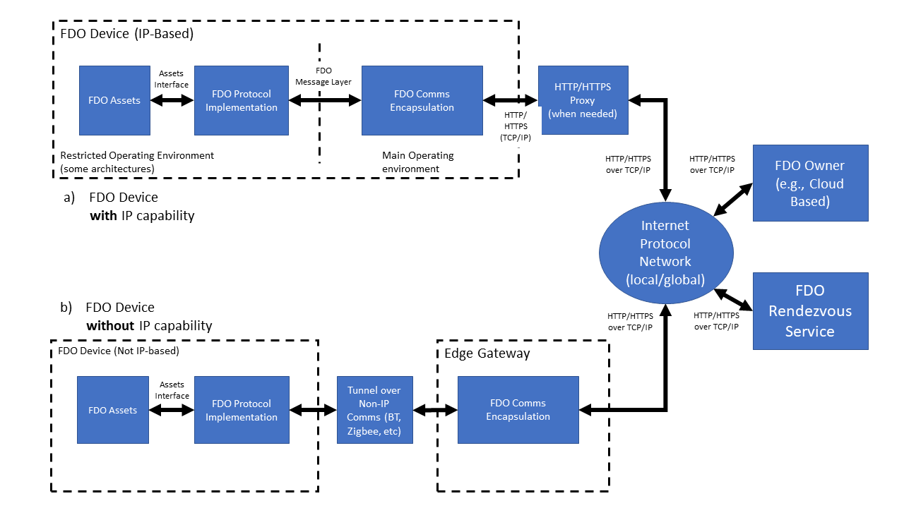
Figure 1 describes the way in which FDO data is transported. FDO protocols are defined in terms of a FDO message layer (§ 2.1 Message Passing Protocol) and an encapsulation of these messages for transport to FDO network entities (§ 4 Data Transmission).
FDO Devices MAY be either natively IP-based or non-IP-based. In the case of FDO Devices which are natively connected to an IP network, the FDO Device is capable of connecting directly to the FDO Owner or FDO Rendezvous server.
The initial connection of the Device to the IP network is outside the scope of this document. FDO is designed to allow an explicit or implicit HTTP proxy to operate as a network entry mechanism, when HTTP or HTTPS transport is used. The decision to use this or another mechanism is also out of scope for this document.
FDO Devices which are not capable of IP protocols MAY use FDO by tunneling the FDO message layer across a reliable non-IP connection. FDO messages implement authentication, integrity, and confidentiality mechanisms, so any reliable transport is acceptable.
The FDO message layer also permits FDO to be implemented end-to-end in a co-processor, Trusted Execution Environment, or Restricted Operating Environment (ROE). However, security mechanisms must be provided to allow credentials provisioned by FDO to be copied to where they are needed. For example, if FDO is used to provision a symmetric secret into a co-processor, but the secret is used in the main processor, there needs to be a mechanism to preserve the confidentiality and integrity of the secret when it is transmitted between the co-processor and main-processor. This mechanism is outside the scope of this specification.
1.7. FIDO Device Onboard Base Profile (Normative)
This section is normative
This section defines a base profile that is normative for all compliant FDO implementations. This profile constitutes base connectivity for FDO components.
This section references protocol entities. These are defined in: § 2.3 Protocol Entities
1.7.1. Capabilities and Versioning
FDO implementations with support for version 2.0 or later SHALL support the CapabilityFlags and VendorCapFlags mechanism (see § 3.3.2 CapabilityFlags & VendorCapFlags), including the version negotiation mechaism in section § 3.3.3.1 Version Negotiation.
There is no requirement in this profile for support of specific versions of FDO.
1.7.2. Protocols
FDO entities SHALL support transport protocols as follows:
| Entity | Protocol | Requirement |
|---|---|---|
| Rendezvous Server | TO0 & TO1 | HTTP and HTTPS |
| Owner | TO0 & TO2 | HTTP and HTTPS |
| Device | TO1 & TO2 | Either HTTP or HTTPS |
1.7.3. Device Attestation
Regarding Device attestation, using Entity Attestation Token (EAT) cryptography (i.e., Device attestation), FDO components SHALL support attestation and verification using cryptography:
-
ECDSA signatures, based on SECP256R1 or SECP384R1, encoded using X5CHAIN or X.509
as follows:
| Entity | Protocol | Requirement |
|---|---|---|
| Rendezvous Server | TO1 | Verify any attestation, as above. |
| Owner | TO2 | Verify any attestation, as above. |
| Device | TO2 |
Generate at least one attestation signed with cryptography, above. Although it is legal for a device to support multiple cryptographic options for device attestation, we anticipate that the device manufacturer will pre-configure a single cryptographic attestation for purposes of FDO. |
1.7.3.1. Post Quantum Safe Cryptography
Support for Post Quantum Safe (aka PQ Safe) cryptography is highly recommended, but not mandated as of this writing. Implementations are strongly urged to prepare for and (later) backfill support for PQ Safe cryptography into their implementations of FDO.
Please watch the FIDO Alliance site for updates on support for PQ Safe cryptography in FDO.
1.7.4. Delegation and Capability Flags
All FIDO Device Onboard entities that support the base profile MUST support capability flags to enable or disable Delegation.
To implement the base profile, a FDO entity SHOULD support Delegation. A Device, Owner, or Rendezvous Server that otherwise supports the profile MAY disable Delegation using a capability flag.
1.7.5. Ownership Vouchers
Regarding Ownership Vouchers generated, extended and verified, FDO components SHALL be able to process Ownership Vouchers with cryptography:
-
Hash: SHA256 or SHA384
-
MAC: HMAC-SHA256 or HMAC-SHA384
-
Signature:
-
RSAPKCS and RSA2048RESTR public keys and signatures, encoded in X.509 (i.e., RSAPSS keys are not part of the profile).
-
ECDSA public keys and signatures, based on SECP256R1 or SECP384R1 encoded using X.509 or X5CHAIN
-
as follows:
| Entity | Protocol/Activity | Requirement |
|---|---|---|
| Owner | Receive Ownership Voucher from Supply Chain | Verify all combinations, as above |
| Rendezvous Server | TO0 | Verify all combinations, as above |
| Owner | TO2 | Verify all combinations, as above. |
| Device | TO1 & TO2 |
Verify at least one combination of cryptographic options (hash, MAC, signature), as above. Although it is legal for a device to support multiple cryptographic options for Ownership Voucher attestation, the manufacturer is expected to "seed" the Ownership Voucher with a single option that works for the host; subsequent entities must extend the Ownership Voucher using the same cryptographic options, so that the Device is only required to implement a single option. |
1.7.6. Session cryptography (TO2 protocol)
FIDO Device Onboard components SHALL support the following session cryptography:
-
Key Exchange using ECDH256, ECDH384, DHKEXid14, DHKEXid15, ASYMKEX2048, ASYMKEX3072
-
Confidentiality & integrity:
-
authenticated encryption: AES-GCM or AES-CCM, as given by
AESType -
encrypt-then-mac: as given by
AESPlainTypewith HMAC-SHA256 or HMAC-SHA384.
-
Support shall be as follows:
| Entity | Protocol/Activity | Requirement |
|---|---|---|
| Owner | TO2 | Generate and verify any combination of the above |
| Device | TO2 | From above, generate and verify at least one key exchange and one "Confidentiality & integrity" selection. |
2. Protocol Description
-
HTTP/HTTPS (All current implementations of FDO) use this mechanism
-
Constrained Application Protocol (CoAP) [RFC7252]
-
TCP or TCP/TLS streams
-
Non-Internet protocols, such as Bluetooth® specification or USB specification
FDO messages are formatted and encoded as described in subsequent sections
2.1. Message Passing Protocol
This section is normative
FDO messages are defined in § 5 Detailed Protocol Description. A message is logically encapsulated by a protocol-dependent header containing the message type, protocol version, and other transmission-dependent characteristics, such as the message URL and message length in bytes. The message header is transmitted differently for different transport protocols. For example, the message header can be encoded into the HTTP header fields.
The message body is a CBOR [RFC8949] object, as described in the following sections.
Entity Attestation Tokens within FDO are also encoded in CBOR.
2.2. FIDO Device Onboard CBOR Document Conventions
This section is normative
The ultimate goal of this document is to define a number of protocols, each of which is a specific flow of messages. The messages are defined by base and composite data types.
This document specifies these items using CDDL [RFC8610].
Many CDDL structures in this document refer to CDDL arrays. In the specification, it is easier to refer to the elements by their CDDL key or their CDDL type; the reader will infer the array index.
CDDL permits array entries to have a CDDL
key (e.g., [key_of_this_int: int]), where the CDDL key
(key_of_this_int) for an array entry exists only in the
specification. This mechanism is used for common types
within an array. Another mechanism used is to create a type instance and
use it only in one context (deviceInfo = tstr) and refer to the type.
In either case, individual fields are represented using a dot syntax, to indicate containment of one CDDL/CBOR construct inside another. This does not imply in specific containment (i.e., whether maps or arrays). Protocol messages also use the protocol name with a dotted syntax.
For example:
TO2.HelloDeviceProbe.sugar
refers to the 6th element of the TO2.HelloDeviceProbe array, which has type "octet[16]".
Where COSE and EAT complex objects comprise an entire message, the payload entries are used as if they were part of the base message. So:
TO2.ProveOVHdr20.OVPubKey
is a useful shorthand for:
TO2.ProveOVHdr20.CoseSignature.payload.$SigningPayloads.TO2ProveOVHdrPayload.OVPubKey
Similarly, in this array:
to1dBlobPayload = [
    to1dRV:       RVTO2Addr, ;; choices to access TO2 protocol
    to1dTo0dHash: Hash       ;; Hash of to0d from same to0 message
    DelegateChain .cbor CertChainOrNull ;; Optional - Delegate
]
the first element can be referenced as to1dRV or RVTO2Addr, and
the reader will infer the element in to1dBlobPayload[0].
Examples of actual messages are presented in pseudo-JSON. The reader will understand that this refers to CBOR, and convert appropriately. For example:
[ ['str1',3] ]
refers to a CBOR array with 1 element, containing a CBOR array with 2 elements, the first being a text string (tstr) and the second being an unsigned integer (uint).
Base types from the CDDL specification are heavily used, especially as
defined in [RFC8610], see the standard prelude in Appendix D or that document. The
CBOR "hash" representation (e.g., #0), also defined in the CDDL specification, is
also used herein.
CDDL plug-and-socket is used to simplify reference to COSE and EAT
tokens. Rather than define the entire token for each message where it
is referenced, the token is defined with payload "plugs" (e.g.,
$COSEPayloads) that are filled in for each message, such as:
$COSEPayloads /= ( thisMessagePayload )
So a message can be read as: "this message is a COSE object with the following payload." While this does not generate the tightest CDDL specification for each message type, we feel it is easier to understand.
2.3. Protocol Entities
This section is normative
See Figure 2 for a diagram of FDO Entities and their protocol interconnections.
-
Manufacturer (Mfg): Device manufacturer. A FDO application runs in the factory, which implements the initial communications with the Device ROE, as part of the Device Initialize Protocol (DI) or appropriate substitute.
-
Device: The device being manufactured, later the device being provisioned. This device has hardware and software configured on it, including a Device ROE and a Management Agent. In the following documentation, a FDO enabled Device is capitalized, to distinguish it from reference to the generic meaning of "device".
-
Device ROE: A Restricted Operating Environment within the Device. In some Devices, this is a co-processor or a special processor mode that enables a small kernel of code to run, with credentials to prove its authenticity.
-
Device ROE App: This is the application that is installed in the ROE of the device to provide the FDO capabilities on the device. When we informally refer to the Device ROE as an endpoint to a protocol, we always mean the Device ROE App.
-
Owner: This is an entity that is able to prove ownership to the Device using an Ownership Voucher and a private key for the last entry of the Ownership Voucher (the “Owner Key”). Various members of the supply chain might have bought and sold the device while it was still “boxed,” acting as owners, but without powering on the device. The final owner in the chain uses the Owner Onboarding Service to provision the device, and then controls it across a network using a Manager.
-
Manager also called a Management Service: The entity that manages devices via a network connection. This can range from an application on a user’s computer, phone or tablet, to an enterprise server, to a cloud service spanning multiple geographic regions. The Manager interacts with the Device using the Management Agent. Commonly, the Manager is an existing IoT or cloud management service that is provisioned using FDO, so that it operates the same as if it were manually provisioned.
In some cases, the owner elects to subscribe to a cloud service and proxy his ownership, so that the Manager controls the ownership credentials of the owner.
The common industry term "Device Management Service" (DMS) is shortened in this document because the word Device is used frequently.
-
Management Agent: The entity on the device that uses the FDO Device software to allow the device ownership to be transferred using FDO protocols. During FDO operation, the Management Agent interacts with the Management Service via the ServiceInfo key-value pairs.
-
Owner Onboarding Service: This is an entity constructed to perform FDO protocols on behalf of the Owner. The Owner Onboarding Service is an application that executes on some platform already controlled by the Owner. After the protocols are completed, the Owner Onboarding Service transfers control of the device to the Owner’s Management Service, and never interacts with the Device again. In FDO, the Owner Onboarding Service is a component of the Management Service, rather than a separate network service.
-
Rendezvous Server: A network server or service (e.g., on the Internet) that acts as a rendezvous point between a newly powered on Device and the Owner Onboarding Service. It is expected that Internet versions of the Rendezvous Server will comprise multiple actual servers and service points; the reader will understand that Rendezvous Server in this document applies to the aggregate service.
2.3.1. Entity Credentials
Each of the entities above identifies itself in FDO protocols using cryptographic credentials. These are:
-
Device Attestation Key : FDO uses cryptographic device attestation based on a signed Entity Attestation Token ([EAT]). The protocol can support many cryptographic mechanisms for device attestation but this spec supports the basic capability: ECDSA. For ECDSA, there is a private key that is provisioned into the device, such as when the CPU or board is manufactured, for establishing the trust for a Restricted Operating Environment (ROE) that runs on the device. When signed by the device attestation key, this provides evidence of the code being executed in the ROE.
-
Ownership Credential Key Pair: This is a key pair that serves temporarily to identify the current owner of the device. When the device is manufactured, the manufacturer uses a key pair to put in an initial ownership credential. Later, the protocols conspire specifically to replace this credential with a new ownership credential, effecting ownership transfer.
-
Delegate Key Pair: When delegation is invoked, the Delegate Certificate combines with the Delegate Key Pair to substitute for the Ownership Credential Key Pair. See § 1.3.1 Delegation and Delegated Owners.
-
The Device Credential does not identify the owner in general, it identifies the owner for the purposes of ownership transfer. The device credential from the manufacturer, stored in the device, must match the credential at one side of the ownership voucher. That is all. It is not intended that this key pair permanently identify the manufacturer or any of the parties in the ownership voucher. On the contrary, we expect that the manufacturer can use different keys over time and the owners will also use different keys over time, specifically to obscure their identity in the FDO protocols and increase of the robustness of FDO.
2.3.2. Management Agent/Service interactions using ServiceInfo
In the Transfer Ownership Protocol 2 (TO2), after mutual trust is proven, and a secure channel is established, key-value pairs are exchanged. This is a mechanism for interaction between the Management Agent and Management Service using the TO2 protocol as a secure transport. The amount of information transferred using this mechanism is not specifically constrained by the TO2 protocol, but some structure is imposed in the definition of ServiceInfo (Section 5.2.5). The intent is to allow the Management Service to provision sufficient keys, data and executables to the Management Agent so that they are enabled to interact securely for the life of the device.
For example, a Management Agent might send a Public Key Cryptography Standards (PKCS#10) Certificate Signing Request (CSR) to the Management Service in a Device ServiceInfo key-value pair, which can use a certificate authority (CA) to provision a X.509 certificate, trusted by itself, and send that certificate back to the Management Agent in PKCS#7 format, all using an Owner ServiceInfo key-value pairs.
The flows of ServiceInfo information between the Owner and the Management
Service, and between the Device and the Management Agent, are outside the scope
of this document.
It is legal for a ServiceInfo interaction to be empty (i.e.,
IsMoreServiceInfo is False on the first ServiceInfo message.
ServiceInfo provides a key-value pair mechanism. The namespace of keys is divided into module-specific spaces and key attributes allow for downloading of data files or executable code (e.g., installation scripts) using the trust provided by FDO.
Note: Since the initial publication of FIDO Device Onboard, the term FSIM has come to be used as an abbreviation for "FDO ServiceInfo Module".
2.4. Protocol Entity Interactions
This section is normative
The following diagram shows the interaction between the protocol entities in the FDO Protocols:
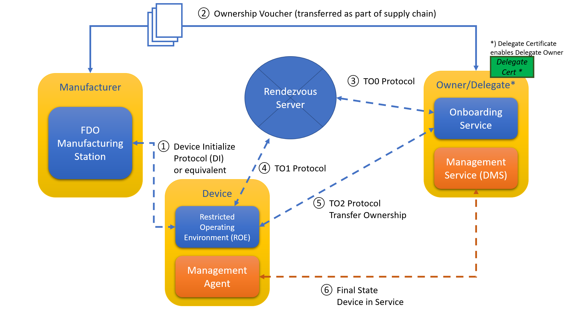
The following sections define these protocols.
It is expected the “final state” protocol (bottom arrow in the diagram) can be a pre-existing protocol between a Management Agent and Management Service that exist independently of FDO. FDO serves to provide credentials rapidly and securely so that the pre-existing software is able to take over and operate as if it were manually configured. FDO is not used further by the device or owner unless the owner wishes to re-provision the device, such as to effect another ownership transfer.
Some of the interactions between entities are not defined in the protocols:
-
The manufacturer creates an Ownership Voucher based on the credentials in the Device Initialize Protocol (DI). The Ownership Voucher is a digital document that provides the Owner with the credentials to take ownership of the Device. It is extended with each owner while the device is offline (i.e., boxed or shipped) between Manufacturer and Owner. The Ownership Voucher is defined in [§ 1.7.5 Ownership Vouchers]. This specification does not indicate how the Ownership Voucher is transported from the Manufacturer to the Owner Onboarding Service, where it is used in the FDO protocols.
-
The interaction between the Device ROE App and the Management Agent is system dependent.
-
The interaction between the Owner’s Management Service and the Owner Onboarding Service is dependent on the implementation of these two components.
In addition, the Device Initialize Protocol (§ 5.2 Device Initialize Protocol (DI)) is non-normative.
When Delegation (§ 3.5 Delegation) is used, one or more Devices can be delegated using a Delegate Certificate. The protocol interactions look the same, but the Owner uses a Delegate Certificate to authorize to the Device, instead of the Owner key.
2.5. Protocols
The following protocols are defined as part of FDO. Each protocol is identified with an abbreviation, suitable to use as a programming prefix. The abbreviations are also used in this discussion.
Table‑. FIDO Device Onboard Protocols
| Protocol Name | Abbr. | Function |
|---|---|---|
| Device Initialize Protocol (DI) | DI | Insertion of FDO credentials into device during the manufacturing process. |
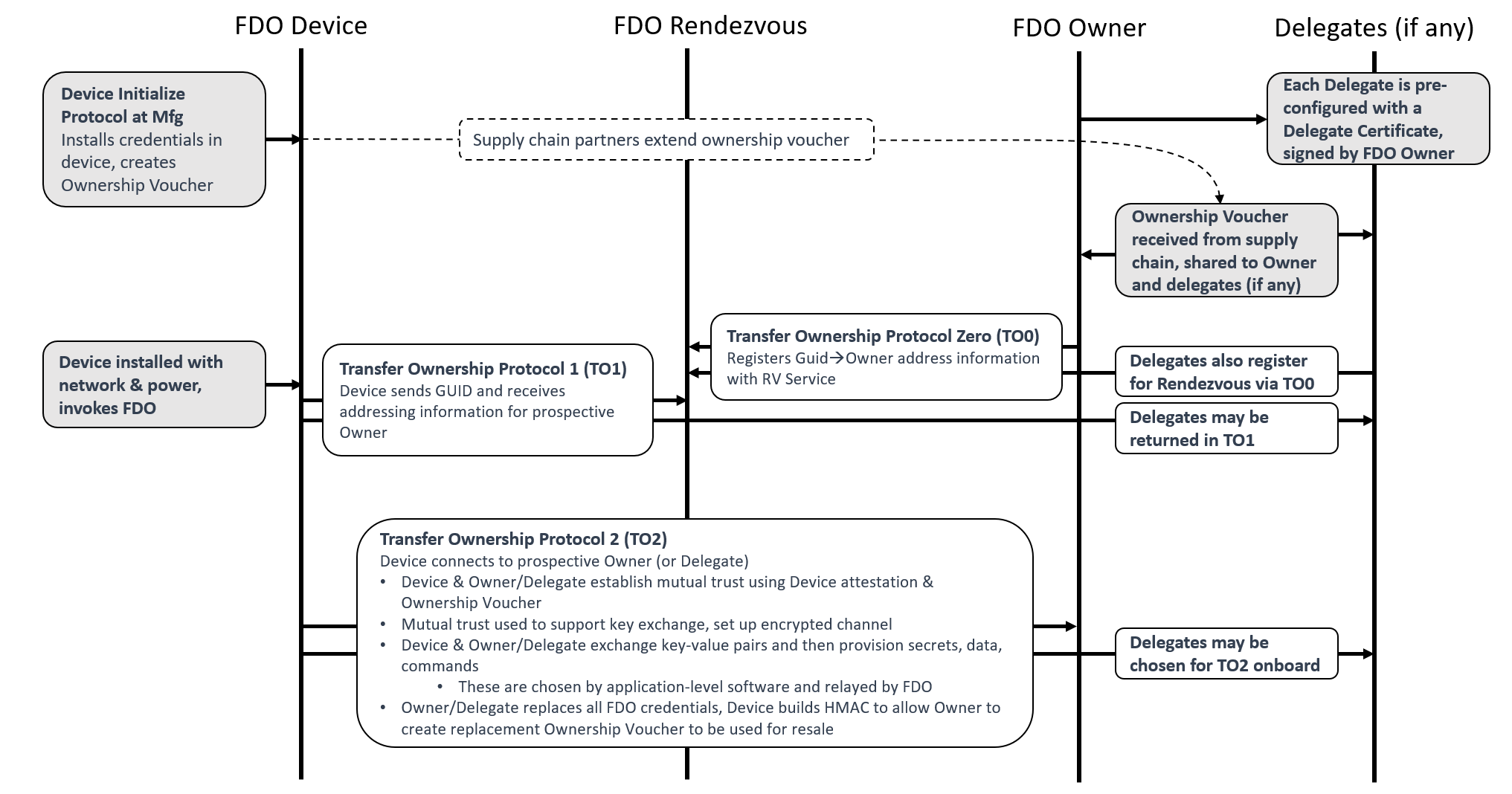
| Transfer Ownership Protocol 0 (TO0) | TO0 | FDO Owner identifies itself to Rendezvous Server. Establishes the mapping of GUID to the Owner IP address. |
| Transfer Ownership Protocol 1 (TO1) | TO1 | Device identifies itself to the Rendezvous Server. Obtains mapping to connect to the Owner’s IP address. |
| Transfer Ownership Protocol 2 (TO2) | TO2 | Device contacts Owner. Establishes trust and then performs Ownership Transfer. |
The following figure shows a graphical overview of these protocols. Graphical representations of each protocol are presented with the protocol details.
2.5.1. Device Initialize Protocol (DI)
This section is non-normative
The non-normative Device Initialize Protocol (DI) provides an example of a protocol that runs within the factory when a new device is completed. The protocol’s function is to embed the ownership and manufacturing credentials into the newly created device’s ROE. This prepares the device and establishes the first in a chain for creating an Ownership Voucher with which to transfer ownership of the device.
The Device Initialize Protocol assumes that the protocol will be run in a safe environment. The trust model is Trust on First Use (TOFU). When possible, the DI Protocol can use write-once memory to ensure the Device is not erased or reprogrammed after factory use. When no such hardware is available, it might be possible to reprogram the device, so as to create alternate FDO credentials.
The Device Initialize Protocol starts with:
-
The physical device and the FDO Manufacturing Component attached to a local network within the factory.
-
The FDO Manufacturing Component has access to:
-
A key pair for device ownership, which will be used to create device credentials in the device and the Ownership Voucher. This key pair does not specifically identify the manufacturer (e.g., it is not in a certificate) and can be changed from time to time, so long as the Device Credential refers to the same key pair as the Ownership Voucher for that device.
-
Device description string (tstr), configured by the manufacturer.
-
Device ROE running the FDO application. In one implementation, the Device PXE-boots into this application.
The Device Initialize Protocol ends with:
-
The FDO Manufacturing Component has information and credentials to create an Ownership Voucher for the device or has the Ownership Voucher itself.
-
The Device has ownership and manufacturer credentials stored in its ROE. The Device SHOULD arrange to protect these credentials. Ideally:
-
Only the Device ROE software is able to access these credentials.
-
The credentials are protected against modification by non-FDO programs.
-
Any modification of the credentials by non-FDO programs (despite measures above) is detectable.
-
-
The Device is ready to be powered off and boxed for shipment. No further network attachment is necessary.
-
The Device has a GUID that can be used to identify it to its new owner. This GUID is also known to the FDO Manufacturing Component, and is in the Ownership Voucher. The GUID is not a secret. Specifically, the GUID is intended to be visible to the Owner when the device shipped in a box, perhaps being on the box itself with a bar code, perhaps being on the bill of lading. The GUID is used for one FDO transfer of ownership only; after Transfer Ownership Protocol 2, the GUID is replaced, and the Device has no memory of the original GUID.
-
a non-volatile memory can be programmed directly with FDO device credentials
-
a secured version of the DI protocol can be implemented using TLS credentials statically programmed into each side of the connection, authorized by a trusted person at the DI site.
2.5.2. Transfer Ownership Protocol 0 (TO0)
Transfer Ownership Protocol 0 (TO0) serves to connect the Owner Onboarding Service with the Rendezvous Server. In this protocol, the Owner Onboarding Service indicates its intention and proves it is capable of taking control of a specific Device, based on the Device’s current GUID.
Transfer Ownership Protocol 0 starts with:
-
A presumed Device that has undergone the Device Initialize Protocol (DI) and thus has credentials in its ROE (DeviceCredential) identifying the Manufacturer public key that is in the Ownership Voucher. The Device is not a party to this protocol, and can be powered off, in a box, or in transit when the protocol is run.
-
The Owner Onboarding Service has access to the following:
-
An Ownership Voucher, whose last Public key belongs to the Owner, and the GUID of the device, which is also authorized by the Ownership Voucher.
-
The private key that is associated with the Owner’s public key in the Ownership Voucher.
-
An IP address from which to operate. This IP address need bear no relationship to the service addresses that are used by the Owner. The Owner can take steps to hide its address, such as allocating it dynamically (e.g., using DHCP) or using an IPv6 privacy address. The motivation for hiding this IP address is to maintain the privacy of the Owner from the Rendezvous Server or from anyone monitoring network traffic in the vicinity of the Rendezvous Server. This can never be done for sure; we think of it as raising the bar on an attacker.
-
-
The Rendezvous Server has some way to trust at least one key in the Ownership Voucher. For example, the Manufacturer has selected the Rendezvous Server, then the Rendezvous Server might be aware of the Manufacturer’s public key used in the Ownership Voucher.
Transfer Ownership Protocol 0 ends with:
-
The Rendezvous Server has an entry in a table that associates, for a specified interval of time, the Device GUID with the Owner Onboarding Service’s rendezvous 'blob.' The blob contains an array of {DNS name, IP address, port, protocol}.
-
The Owner Onboarding Service is waiting for a connection from the Device ROE at this DNS name and/or IP address for this same amount of time.
If the Device ROE appears within the set time interval, it can complete Transfer Ownership Protocol 1 (TO1). Otherwise, the Rendezvous Server forgets the relationship between GUID and Rendezvous 'blob.' A subsequent TO1 from the Device ROE will return an error, and the Device will not be able to onboard. The Owner Onboarding Service can extend the time interval by running Transfer Ownership Protocol 0 again. It can do so from a different IP address.
In the case of a device being connected to a cloud service, the Owner Onboarding Service typically would repeatedly perform the TO0 Protocol until all devices known to it successfully complete the TO2 Protocol. In the case of a Device being connected using an application program implementation of the Owner Onboarding Service, the Owner might arrange to turn on the Owner Onboarding Service shortly before turning on the device, to expedite the protocol.
The Rendezvous Server is only trusted to faithfully remember the GUID to Owner blob mapping. The other checks performed protect the server from DoS attacks, but are not intended to imply a greater trust in the server. In particular, the Rendezvous Server is not trusted to authorize device transfer of ownership. Furthermore, the Rendezvous Server never directly learns the result of the device transfer of ownership.
2.5.3. Transfer Ownership Protocol 1 (TO1)
Transfer Ownership Protocol 1 (TO1) is an interaction between the Device ROE and the Rendezvous Server that points the Device ROE at its intended Owner Onboarding Service, which has recently completed Transfer Ownership Protocol 0. The TO1 Protocol is the mirror image of the TO0 Protocol, on the Device side.
The TO1 Protocol starts with:
-
A Device that has undergone the Device Initialize Protocol (DI) and thus has credentials (DeviceCredential) in its ROE identifying the particular Manufacturer Public Key that is in the Ownership Voucher. The Device is ready to power on.
-
An Owner Onboarding Service and Rendezvous Server that have successfully completed Transfer Ownership Protocol 0:
-
The Rendezvous Server has a relationship between the GUID stored in the device ROE and a rendezvous 'blob', as described above.
-
The Owner Onboarding Service is waiting for a connection from the Device ROE on the network addresses referenced in the rendezvous 'blob.'
If these conditions are not met, the Device will fail to complete the TO1 Protocol, and it will repeatedly try to complete the protocol with an interval of time between tries. The interval of time SHOULD be chosen with a random component to try to avoid congestion at the Rendezvous Server.
After the TO1 Protocol completes successfully:
-
The Device has rendezvous information sufficient to contact the Owner Onboarding Service directly.
-
The Owner Onboarding Service is waiting for a connection from the Device ROE on the network addresses referenced in the rendezvous 'blob.' I.e., it is still waiting, since it does not participate in the TO1 Protocol.
2.5.4. Transfer Ownership Protocol 2 (TO2)
Transfer Ownership Protocol 2 (TO2) is an interaction between the Device ROE and the Owner Onboarding Service where the transfer of ownership to the new Owner actually happens.
Before the TO2 Protocol begins:
-
The Owner has received the Ownership Voucher, and run Transfer Ownership Protocol 0 to register its rendezvous 'blob' against the Device GUID. It is waiting for a connection from the Device ROE on the network addresses referenced in this 'blob.'
-
The Device has undergone the Device Initialize Protocol (DI) and thus has credentials (DeviceCredential) in its ROE identifying the particular Manufacturer’s Public Key that is (hashed) in the Ownership Voucher.
-
The Device has completed Transfer Ownership Protocol 1 (TO1), and thus has the rendezvous 'blob', containing the network address information needed to contact the Owner Onboarding Service directly.
After the TO2 Protocol completes successfully:
-
The Owner Onboarding Service has replaced all the device credentials with its own, except for the Device’ attestation key. The Device ROE has allocated a new secret and given the Owner a HMAC to use in a new Ownership Voucher, which can be used for resale. See § 6 Resale Protocol.
-
The Owner Onboarding Service has transferred new credentials to the Device ROE in the form of key-value pairs. These credentials include enough information for the Device ROE to invoke the correct Management Agent and allow it to connect to the Owner’s Management service. The set of parameters is given in the following messages, although the OwnerServiceInfo is an extensible mechanism. See § 3.9 ServiceInfo and Management Service – Agent Interactions.
-
TO2.SetupDevice20 (§ 5.5.11 TO2.SetupDevice20, Type 87)
-
TO2.OwnerSvcInfo20 (§ 5.5.13 TO2.OwnerSvcInfo20, Type 89)
-
-
The Owner Onboarding Service has transferred these credentials to the Owner’s Manager, which is now ready to receive a connection from the Device.
-
The Device ROE has received these credentials, and has invoked the Management Agent and given it access to these credentials.
-
The Management Agent has received these credentials is ready to connect to the Owner’s Manager.
In a given Device, there might be a distinction between: the Device ROE and the Management Agent; and between the Owner Onboarding Service and the Owner’s Manager:
-
The Device ROE performs the FDO protocols and manipulates and stores FDO credentials. The Device ROE is likely to store other credentials and perform other services (e.g., cryptographic services) for the device.
-
The Device itself runs its basic functions. Amongst these is the Management Agent, a service process that connects it to its remote Manager. This software is often called an “agent”, or “client.” We intend that this software can be a pre-existing agent for the Management Service chosen by the Owner, which can also operate on devices that do not use FDO.
-
The Owner Onboarding Service is a body of software that is dedicated specifically to run the FDO Protocol on behalf of the Manager. For example, this code might have its own IP addresses, so that the eventual Manager IP addresses (which might be well known) are hidden from prying eyes.
-
The Owner Manager is an Internet-resident service that provides management services for the Owner on an ongoing basis. FDO is designed to work with pre-existing management services for IoT devices.
After Transfer Ownership Protocol 2, the FDO specific software is no longer needed until and unless a new ownership transfer is intended, such as when the device is re-sold or if trust needs to be established anew. FDO client software adjusts itself so that it does not attempt any new protocols after the TO2 Protocol. Implementation-specific configuration can be used to re-enable ownership transfer (e.g., a CLI command).
2.6. Routing Requirements
This section is normative
In an IP-based network, the Device must be able to route to the Rendezvous Server and the prospective Owner returned by the Rendezvous Server. A "closed" IP network with no path to the Internet can support FDO if:
-
The Rendezvous Server has a network attachment within the closed network
-
The prospective Owner referenced by the returned RVInfo has a network attachment within the closed network
-
The Device can access a bidirectional route to to the IP address at the above attachments
For example, if the closed network uses addresses 192.168.0.0/16, then the Rendezvous Server and prospective Owner returned by the RVInfo and the Device itself must all have IP addresses within 192.168.0.0/16, and a route must exist between the Device that the other two.
2.7. The Ownership Voucher
This section is normative
The Ownership Voucher is a structured digital document that links the Manufacturer with the Owner. It is formed as a chain of signed public keys, each signature of a public key authorizing the possessor of the corresponding private key to take ownership of the Device or pass ownership through another link in the chain.
The entries also contain a description of the GUID or GUIDs to which they apply, and a description of the make and model of the device.

The signatures in the Ownership Voucher create a chain of trust from the manufacturer to the Owner. The Device is pre-provisioned (e.g., in the Device Initialize Protocol (DI)) with a crypto-hash of A.PublicKey, which it can verify against A.PublicKey in the Ownership Voucher header transmitted in the TO2 protocol. The owner can prove his connection with the Ownership Voucher (and thus his right to take ownership of the Device) by proving its ownership of D.PrivateKey. It can do this by signing a nonce (sometimes called a challenge), and the signature can be verified using D.PublicKey from the Ownership Voucher.
The last entry in the Ownership Voucher belongs to the current owner. The public key signed in that entry is the owner’s public key, signed by the previous owner. We call this public key the “Owner Key.”
In the TO2 Protocol, the Owner proves his ownership to the device using a signature (as above) and an Ownership Voucher that is rooted in A.PublicKey. The Device verifies that the hash of A.PublicKey stored in its ROE matches A.PublicKey in the Ownership Voucher, then verifies the signatures of the Ownership Voucher in sequence, until it comes to D.PublicKey. The Owner provides the Device separate proof of D.PublicKey (the “owner key”), completing the chain of trust. The only private key needed to verify the Owner’s assertion of ownership is the key of the Owner itself. The public keys in the Ownership Voucher (and the public key hash in the Device) are sufficient to verify the chain of signatures.
The public keys in the Ownership Voucher are just public keys. They do not include other ownership info, such as the name of the entity that owns the public key, what other keys they might own, where they are, etc.
The Ownership Voucher is maintained only for the purposes of connecting a particular device with its particular first owner. The entities involved can switch the key pairs they use to sign the Ownership Voucher from time to time, make it more difficult for potential attackers to use the Ownership Voucher as a means to map out the flow of devices from factory to implementation.
Conversely, it is conceivable that a private data structure might contain supply chain identities, allowing the Ownership Voucher to specifically map the identities who signed it. The use of the Ownership Voucher for other than device onboarding is outside the scope of this specification.
When Delegation (§ 3.5 Delegation) is in use, a Delegate Owner onboards on behalf of the Owner. The Ownership Voucher works as above. A Delegate Certificate, signed by the Owner in the Ownership Voucher, permits Delegate Owners to onboard.
Note: The Ownership Voucher signing operation need not be the same as the device attestation operation. For example, a device can use RSA for Ownership Voucher signing and use ECDSA for device attestation. However, the Ownership Voucher signing and key encoding must be consistent across all entries in the ownership voucher. This is required to ensure that the Device is able to process each entry.
2.7.1. FDO Ownership Voucher vs RFC8366 Voucher
The Ownership Voucher in FIDO Device Onboard is distinct from the Voucher Artifact described in RFC8366 ([RFC8366]), although both are structured documents that convey trust. The Ownership Voucher, presented here, conveys trust through the supply chain from the manufacturer, being the original 'owner' of the Device, to the ultimate Owner who will use the Device in a production setting. The Voucher Artifact (RFC8366) is a dynamically generated object which provides an endorsement of the Device from a trusted authority (the "MASA").
3. Protocol Encoding and Primitives
This section is normative
FDO defines base types, composite types (based on the base types), and protocol messages based on the composite types. Persisted Items indicate data structures that need to be persisted on storage and/or transmitted between FDO entities outside the protocol.
Implementors can choose to persist additional data to help in the implementation details.
CDDL
start /= (
    BaseTypes, CompositeTypes,
    DataStructures
    ProtocolMsg
)

DataStructures /= (
    DeviceCredential,  ;; in device
    OwnershipVoucher,  ;; outside device
    DelegateCertificate;; Delegation authorization (where used)
)

DelegateCertificate = X5CHAIN ;; X.509 certificate or cert chain

ProtocolMsg /= (
    ErrorMessage,
    DIProtocolMessages, TO0ProtocolMessages,
    TO1ProtocolMessages, TO2ProtocolMessages
)
3.1. CBOR Message Encoding
FDO uses CBOR message encoding [RFC8949].
Encoded FDO messages MUST follow CBOR length-first core deterministic encoding, as described in [RFC8949], section 4.2.3. This is called "Canonical Encoding" in the earlier CBOR specification, RFC7049, section 3.9.
FDO entities, other than the Device, MUST verify this encoding. The Device SHOULD verify this encoding.
The value null in the text refers to a CBOR null, #7.22 (0xf6), whether explicitly described as a CBOR null or not.
Implementations MUST NOT use CBOR indefinite length. The intent of this restriction is to limit memory usage on a constrained Device.
FDO does not constrain the use of CBOR data types in COSE or EAT data structures, or in ServiceInfo values, except to exclude indefinite length.
When transmitting frames over a stream in FDO, the initial length field’s size is constrained by the FDO protocol. This intended to make it easier for low-level I/O drivers to read entire messages. See section § 4.2 Transmission of Messages over a Stream Protocol.
In cases where CBOR values must be hashed or signed, the payload is
wrapped in a byte string (bstr). This makes it easier for decoders
to determine which CBOR encoded values to include in the computation.
The bstr wrapper itself is generally not included in the hash. COSE
and EAT
use a similar mechanism for "protected header" fields.
3.2. Base Types
CDDL
BaseTypes /= (
    ;; BaseTypes pulled in from CDDL specification
    int, uint,
    bool,
    tstr,
    bstr,

    ;; BaseTypes unique to this specification
    uint8, uint16, uint32,
    msgarray,
    uint16bits
)

;; Defined in CDDL spec and standard prelude
;; This summary is non-normative
;;int    = #0 / #1
;;uint   = #0
;;bool   = #7.20 / #7.21
;;tstr   = #3
;;bstr   = #2
;;any: any single CBOR object

;; Normative specification of specific types used below.
;;
;; Message array, must be encoded as a single byte, see below.
msgarray=#4

;; uint with no more than 16 bits magnitude.
;; We require 1, 2, or 3 byte encoding, although the following CDDL
;; expression permits a longer encoding (see text).
uint16bits = #0 .size 2

;; Type names used in the specification
protver = uint16bits
msglen = uint ;; can be large when PQ-safe crypto used
msgtype = uint16bits
Note: Starting in FDO version 2.0, msglen has been
changed from uint16bits to uint, to reflect the prospect that large
messages can be needed for cryptography that is not compromised by
prospective quantum computers. Since the encoding of this value was
always a CBOR uint (aka #0), this does not change the usual
encoding. However, implementations SHOULD plan to process larger
message sizes than 65536 bytes in the future.
The following types are imported, unchanged, from the CDDL specification [RFC8610], section 3.3:
-
int
-
uint
-
bool
-
tstr
-
bstr
Most FDO integers are subsets of the uint type. To aid the protocol implementation, the requirements for storage are made more explicit, by indicating the storage size:
-
uint8 for 8 bits,
-
uint16 for 16 bits
-
uint32 for 32 bits
The encoding for transmission
MAY be any legal CBOR major type 0 (uint) encoding, so long as the storage
requirement for storing the value is not exceeded (i.e., a 9-byte
encoding for uint 255 still is considered a valid uint8). Owner
and Rendezvous Server implementations MUST check that particular transmitted values are in the range
for the type indicated, and Device implementations
SHOULD so check.
The following types are used for a fixed length stream header and MUST be encoded in a specific manner:
The msgarray type MUST be encoded as a single byte. This array
(major type 4) is
always 5 entries long, so the encoding is exactly: (4<<5)+5 = 0x85.
The uint16bits type MUST be encoded in 1, 2, or 3 bytes. This is
different from the uint16 type, which can have any uint
encoding, but whose value must fit in 16 bits.
The protver type is used to transmit the version of the protocols in
this specification. Its value is always the same for a given protocol run:
protver_value = protocol_major_version * 100 + protocol_minor_version
The specifying authority for FDO must ensure that protocol_minor_version is less than 100.
For this document, the protocol_major_version is 2 and the
protocol_minor_version is 0, so values of the protver type
must always equal 200.
3.3. Composite Types
Composite types are combinations or contextual encodings of base types.
3.3.1. Stream Message
CDDL
;; StreamMsg is designed for use in stream protocols.
;; The stream message always has 5 elements, and its encoding is
;; constrained, as above, so that the array header and first 3
;; elements can be read in a known number of bytes.
StreamMsg = msgarray
StreamMsg = [
    length: msglen, ;; length of the entire StreamMsg in bytes
    type:   msgtype,  ;; message type
    pv:     protver,    ;; protocol version
    MsgProtocolInfo,
    MsgBody
]
;; Protocol specific information, used for maintenance of the
;; entity connection in a specific protocol context
MsgProtocolInfo = {
    ?"token": authtoken ;; copy of HTTP authentication token
}
;; Messages
MsgBody = ProtocolMessage
This type is used for encoding FDO into streaming transports. See section § 4.2 Transmission of Messages over a Stream Protocol.
The StreamMsg data type is designed to guarantee that the message
length is read in the first 4 bytes, assuming msglen is usually less
than 65536. However, implementors are warned that post-quantum
resistant cryptography can cause this assumption to be false in the
future.
All FDO implementations SHOULD place messages into the StreamMsg format before handing them to FDO implementation. This gives the implementation access to required FDO transmitted data, without the need to use device-specific APIs to obtain message data that is encoded in the transport protocol.
3.3.2. CapabilityFlags & VendorCapFlags
CapabilityFlags = bstr
VendorCapFlags = [ tstr* ] ;; vendor-specific capability flags
(For individual vendor capability flags, see table below)
Starting with FDO version 2.0, capability flags are added. This mechanism permits a protocol entity to inform its peer about specific capabilities, such as versions of FDO and optional features. A vendor capability flags mechanism is also provided to allow vendors to add their own extensions to the FDO protocol.
3.3.3. CapabilityFlags
Each protocol (DI, TO0, TO1, TO2) transmits capability flags in the
initial message from each side of the connection. Each side of the
connection uses the capability flags to determine how to proceed and
whether the peer can support specific protocol features. The
requester can restart the connection if capability flags indicate a
different initial message is preferable. In this case, the requester
SHOULD send an Error message (CHANGE_CAP_ERROR) to allow the
receiver to clean up the abandoned connection.
CapabilityFlags are transmitted as a CBOR bstr. Only flags with a 1
value are transmitted. Any bits after the end of the transmitted
bstr are assumed to have zero (0) value. Thus a CapabilityFlags
value with 1 bits in only the first byte is transmitted as a bstr of
length 1, normally encoded as a bstr of short length with one data byte.
The table below lists the definitions of all flags used for CapabilityFlags field in all messages.
A server can include additional capabilities that were not requested
by the Device. If the Device chooses to activate one of these
capabilities, it can abandon the existing connection and restart with
this capability listed. The Device SHOULD send an Error message
(CHANGE_CAP_ERROR) when it abandons the initial connection request.
Table -. Capability Flags
| Name | Bit | Byte, Mask | Meaning |
Capb0SupFDO10
| 0
| byte 0, 0x01
| Sender Supports FDO 1.0 |
Capb0SupFDO11
| 1
| byte 0, 0x02
| Sender Supports FDO 1.1 |
Capb0SupFDO20
| 2
| byte 0, 0x04
| Sender Supports FDO 2.0 |
3,4,5,6
| byte 0, 0x78
| Reserved, must be zero | |
Capb0SupDELEG
| 7
| byte 0, 0x80
| Sender Supports Delegation |
≥8
| byte ≥1
| Reserved |
3.3.3.1. Version Negotiation
The FDO Owner and Rendezvous Server MUST implement FDO version negotiation. FDO Devices supporting a protocol version 2.0 SHOULD implement FDO version negotiation
Although earlier versions of FDO did not support capability flags, it is possible for a Device that supports only these versions to implement a minimal query for capabilities as follows. To do this, the Device implements the initial two messages from FDO 2.0:
-
Device sends FDO 2.0 initial message with capability flags set to include supported versions (e.g., Capb0SupFDO10 | Capb0SupFDO11).
-
Owner or Rendezvous Server returns FDO 2.0 response message with capability flags set to indicate supported protocol versions. In this case, it returns the oddity of a FDO 2.0 message indicating that FDO 2.0 is not supported, but FDO 1.1 is supported.
-
Device chooses the version 1.1, sends an error message with code SWITCH_VERSION
-
Device restarts the protocol using version 1.1
If the server does not support FDO 2.0, the server will abort the initial connection. In this case, the client can try an earlier version (i.e., version 1.0 or version 1.1), supported in the client, in the hopes that this will yield a successful connection.
Obviously, if the client and server do not have a common supported version, the FDO protocol connection between them is destined to fail. However, the logs from version negotiation can still help to determine this problem.
Note: The version negotiation protocol presented here is not protected by signatures. Hence it is vulnerable to network-level attacks. If the FDO Owner is aware of a vulnerable version, it MUST NOT select this version, even if this is the only version proposed by the Device. In such a case, the Device can be re-manufactured to support a non-vulnerable version of FDO. Alternately, the Device and Owner MAY be placed in a closed network environment which is guaranteed free from attackers. Then FDO can be used safely, and can even upgrade the device for onboarding outside this environment.
3.3.3.2. VendorCapFlags
Vendors supporting FDO MAY include vendor-specific flags to
indicate vendor-specific optional capabilities. Vendor-specific flags
are transmitted as an array of text strings (tstr), each of which
indicates a specific vendor capability. Vendor specific capabilities
can be registered with the FIDO Alliance to ensure uniqueness, but
their use can be determined and documented by individual implementors
or vendors of FDO.
To request a vendor flag, the FDO Device includes its CBOR
tstr name the VendorCapFlags array sent by the client intial
protocol message. If the capability is supported by the server, and
the server wishes to enable the capability, the same flag string SHALL
BE included in the server’s initial protocol message VendorCapFlags.
This permits the FDO Device to confirm that the capability is
known to and accepted by the server. A device or server which
supports a given capability MAY choose not to offer this capability by
leaving it out of the VendorCapsFlags array. Determining when this is
appropriate is outside the scope of this specification.
Vendor flag strings SHALL use Reverse Domain Name Notation
(e.g., com.example.myvendorstring), so that each string identifies
the vendor that has created it. Vendors are encouraged, but not
required, to submit vendor flag string names and mechanisms to
the FIDO Alliance so that they can be publicly documented.
Implementations SHOULD do their best to minimize the threat of Downgrade or Versioning attacks, where a bad actor intercepts a message, and adds, deletes or changes the vendor flags to encourage the recipient to use a less secure code-path. Analysis of how this can be accomplished is considered to be implementation-specific.
3.3.4. Hash / HMAC
CDDL
Hash = [
    hashtype: int, ;; negative values possible
    hash: bstr
]
HMac = Hash
hashtype = (
    SHA256: -16,
    SHA384: -43,
    HMAC-SHA256: 5,
    HMAC-SHA384: 6
)
Crypto hash, with length in bytes preceding. Hashes are computed in accordance with [FIPS-180-4].
See COSE assigned numbers [IANA-COSE-ALGS-REG] for the source of the values above. However, this document is normative for the numbers chosen in 'hashtype.'
A HMAC [RFC2104] is encoded as a hash.
The size of the hash and HMAC functions used in the protocol depend on the size of the keys used for device and owner attestation. The following table lists the mapping. The hash and HMAC that are affected by the size of device and owner attestation keys are listed as follows:
-
Hash of device certificate in Ownership Voucher (
OVEntry...OVEntryPayload.OVEHashHdrInfo) -
Hash of previous entry in Ownership Voucher entries, also the hash of header in Ownership Voucher entry zero (
OVEntry...OVEntryPayload.OVEHashPrevEntry) -
Public key hash in Ownership Credentials (
DeviceCredential.DCPubKeyHash) -
Hash of to0d object (TO0.OwnerSign...to1dTo0dHash)
-
HMAC generated by device (DI.SetHMAC.HMac ,TO2.DeviceServiceInfoRdy20.ReplacementHMac, and OwnershipVoucher.OVHeaderHMac)
Table ‑: Mapping of Hash/HMAC Types with Key sizes
| Device Attestation | Owner Attestation | Hash and HMAC Types |
|---|---|---|
| ECDSA NIST P-256 | RSA 2048-bit key | SHA256/HMAC-SHA256 (crypto mismatch) * |
| ECDSA NIST P-384 | RSA 2048-bit key | SHA384/HMAC-SHA384 (crypto mismatch) * |
| ECDSA NIST P-256 | RSA 3072-bit key | SHA256/HMAC-SHA256 |
| ECDSA NIST P-384 | RSA 3072-bit key | SHA384/HMAC-SHA384 (crypto mismatch) * |
| ECDSA NIST P-256 | ECDSA NIST P-256 | SHA256/HMAC-SHA256 |
| ECDSA NIST P-384 | ECDSA NIST P-256 | SHA384/HMAC-SHA384 (crypto mismatch) |
| ECDSA NIST P-256 | ECDSA NIST P-384 | SHA384/HMAC-SHA384 (Crypto mismatch) |
| ECDSA NIST P-384 | ECDSA NIST P-384 | SHA384/HMAC-SHA384 |
For purposes of the above table, RSA keys include key types of RSA2048RESTR, RSAPKCS, and RSAPSS.
Note: Concerning "crypto mismatch" in the table above. The Ownership Voucher and the Device key in these configurations have different cryptographic strengths. Although these are legal configurations, the overall evaluation of the protocol strength is based on the weaker of the two.
Note: Advice has appeared from a variety of government and industry sources that the smaller key sizes listed above can be particularly susceptible to attacks by an early generations of quantum computers. Implementors are encouraged to choose larger key sizes where possible. It is recognized that hardware constraints can force some Devices to use smaller key sizes at present. Please monitor the FIDO Alliance web site (fidoalliance.org) for information on "post quantum" updates to protocols.
3.3.5. SigInfo
CDDL
SigInfo = [
    sgType: DeviceSgType,
    Info: bstr
]

DeviceSgType = [
    StSECP256R1: ES256,  ;; ECDSA secp256r1 = NIST-P-256 = prime256v1
    StSECP384R1: ES384,  ;; ECDSA secp384r1 = NIST-P-384
    StRSA2048:   RS256,  ;; RSA 2048 bit
    StRSA3072:   RS384,  ;; RSA 3072 bit
    StEPID10:    90,     ;; Intel® EPID 1.0 signature (legacy)
    StEPID11:    91      ;; Intel® EPID 1.1 signature (legacy)
]
SigInfo is used to encode parameters for the device attestation signatures.
EPID signature definitions are included for legacy reasons, and are not supported in this version of FDO.
The use of SigInfo is defined in section § 3.6 Device Attestation Sub Protocol.
3.3.6. Public Key
CDDL
PublicKey = [
    pkType,
    pkEnc,
    pkBody
]
;; pkType is a uint8
pkType = (
    RSA2048RESTR: 1, ;; RSA 2048 with restricted key/exponent (PKCS1 1.5 encoding)
    RSAPKCS:      5, ;; RSA key, PKCS1, v1.5
    RSAPSS:       6, ;; RSA key, PSS
    SECP256R1:    10, ;; ECDSA secp256r1 = NIST-P-256 = prime256v1
    SECP384R1:    11, ;; ECDSA secp384r1 = NIST-P-384
)
pkEnc = (
    Crypto:       0      ;; applies to crypto with its own encoding
    X509:         1,     ;; X.509 DER encoding, applies to RSA and ECDSA
    X5CHAIN:      2,     ;; COSE x5chain, an ordered chain of X.509 certificates
    COSEKEY:      3      ;; COSE key encoding
)
;; These are identical
SECP256R1 = (
    NIST-P-256,
    PRIME256V1
)
;; These are identical
SECP384R1 = (
    NIST-P-384
)
The restricted RSA public key, RSA2048RESTR is an RSA key with 2048 bits of base and an exponent equal to 65537. This restriction appears in legacy deployed RSA hardware encryption and decryption modules (see reference in the obsoleted [RFC2313]). In FDO, the distinction of RSA encoding for devices with restricted RSA exponent is needed to ensure that signatures in the Ownership Voucher can be verified in the Device with constrained RSA hardware. Ownership Voucher signers have no other way to know about this limitation.
DER encoding is defined in [ITU-X690-2008].
For X.509 DER key encoding, the ASN.1 field SubjectPublicKeyInfo corresponds
to pkBody. SubjectPublicKeyInfo has fields algorithm and
subjectPublicKey (see [RFC5280]). Additional information is
available in [RFC4055] (Section 1.2) and [RFC3279] section 2.3.1.
-
For
pkTypeofRSA2048RESTRandRSAPKCS, thersaEncryptionobject identifier is{ pkcs-1 1 }. The hash algorithm is SHA256 for RSA 2048 and SHA384 for RSA 3072. -
For
pkTypeofRSAPSS, thersaEncryptionobject identifier is id-RSASSA-PSS, with additional parameters as given in [RFC4055], section 3.1. The hash algorithm is SHA256 for RSA 2048 and SHA384 for RSA 3072.
Elliptical curve cryptography X.509 encoding is defined in [RFC5480], and refers to definitions in [SEC1] and [SEC2].
-
For
pkTypeofSECP256R1, the object identifier isid-ecPublicKeyand the ECParameters specify namedCurve with OIDsecp256r1([RFC5480] section 2.1.1.1). The hash is SHA256. -
For
pkTypeofSECP384R1, the object identifier isid-ecPublicKeyand the ECParameters specify namedCurve with OIDsecp384r1([RFC5480] section 2.1.1.1). The hash is SHA384.
COSE X5CHAIN encoding is given in [COSEX509]. In this case, the public key is wrapped with a X.509 certificate, from which SubjectPublicKeyInfo can be extracted.
-
COSE X5CHAIN permits part or all of a certificate chain to be include. The FDO public key is in the leaf certificate (the "end-entity" key), which is the first element of the x5chain sequence.
-
Other certificate elements, and subsequent certificates in the x5chain, are not used to obtain cryptographic materials to verify the Ownership Voucher. However, public key trust MAY be inferred from the X5CHAIN to inform the confidence in the Ownership Voucher.
The fundamental trust of an Ownership Voucher entry (OVEntry) or
Delegate is the
trust in the organizations that sign it, as expressed through the
signature linkage from the Device Manufacturer through the Owner in
the Ownership Voucher itself. When OVEntry/Delegate contains a certificate
chain, trust in the leaf certificate is possible because the
previously trusted owner cryptographically signed the entire
certificate chain, inherently vouching for every certificate within
it, including the leaf itself.
However, the recipient of the Ownership Voucher MAY choose to require that it be able to verify each certificate chain in each OVEntry/Delegate based on its own CA trust. This can require that the CA trust be known to all participents in the FIDO Device Onboard protocols. This specification is silent on the topic of how an Owner, Device and Rendezvous Server agree on the compatible set of trusted roots.
COSE Key encoding is defined in [RFC9053], section 7, with CDDL definition: COSE_Key.
Signature formats are defined in COSE [RFC9053] and EAT [EAT], and in the associated cryptographic specifications.
3.3.7. COSE Signatures
COSE signatures are used for the ownership voucher. The structure of a COSE object is defined in [RFC9053]. The CDDL below is needed to map the CDDL payload definitions into the message type.
The tag on the COSE_Sign1 object (#6.18) is considered optional in the COSE specification. However, this tag MUST be included in FDO implementations, and is normative COSE encoding for FDO.
;; This is a COSE_Sign1 object:
CoseSignature = #6.18(CoseSignatureBase)

CoseSignatureBase  = [
   protected  : bytes .cbor $$COSEProtectedHeaders,
   unprotected: $$COSEUnprotectedHeaders
   payload:     bytes .cbor $COSEPayloads,
   signature:   bstr
]

;; Use the socket/plug feature of CBOR here.
$$COSEProtectedHeaders /= ()
$$COSEUnprotectedHeaders /= ()
$COSEPayloads /= ()

;; Crypto types missing from COSE.  See appendix.
;;COSEAES128CBC
;;COSEAES128CTR
;;COSEAES256CBC
;;COSEAES256CTR
;; Signing types for EPID (legacy)
;;COSEEPID10
;;COSEEPID11

;; See OVSignType
COSECompatibleSignatureTypes = (
    ES256: -7,  ;; From COSE spec, table 5
    ES384: -35, ;; From COSE spec, table 5
    ES512: -36  ;; From COSE spec, table 5
    RS256: -257,;; From https://datatracker.ietf.org/doc/html/draft-ietf-cose-webauthn-algorithms-05
    RS384: -258 ;; From https://datatracker.ietf.org/doc/html/draft-ietf-cose-webauthn-algorithms-05
)
;; Weird naming for RSA, based on the hash size.  The key size is
;; implied.
;; For RS256, need key size of RSA2048 bits.
;; For RS384, need key size of RSA3072 bits.
The protected, unprotected and payload sections are defined for each signature use, using the socket/plug mechanism with the variables $$COSEProtectedHeaders, $$COSEUnprotectedHeaders and $COSEPayloads.
3.3.8. EAT Signatures
Entity Attestation Token (EAT) signatures [EAT] are used for entity attestation of Devices.
The tag on the COSE_Sign1 object (#6.18), also used for EAT tokens, is considered optional in the COSE specification. However, this tag MUST be included in FDO implementations, and is normative COSE encoding for FDO.
;; This is a COSE_Sign1 object:
EAToken = #6.18(EATokenBase)

EATokenBase  = [
   protected:   bytes .cbor $EATProtectedHeaders,
   unprotected: $EATUnprotectedHeaders
   payload:     bytes .cbor EATPayloadBaseMap
   signature:   bstr
]
EATPayloadBaseMap = { EATPayloadBase }
$$EATPayloadBase //= (
    EAT-[FIDOIOTLABEL] => $EATPayloads,
    EAT-NONCE => Nonce,
    EAT-UEID  => EAT-GUID,
    EATOtherClaims
)
;; EAT claim tags, defined in EAT spec or IANA, see appendix
;; EAT-NONCE
;; EAT-UEID

;; [FDOHANDLE] specific EAT claim tag, see appendix
;;EAT-[FIDOIOTLABEL]
;;EATMAROEPrefix
;;EUPHNonce

;; EAT GUID is a EAT-UEID with the first byte
;; as EAT-RAND and subsequent bytes containing
;; the [FDOHANDLE] GUID
EAT-GUID = bstr .size 17
EAT-RAND = 1

;; Use the socket/plug feature of CBOR here.
$$EATProtectedHeaders //= ()
$$EATUnprotectedHeaders //= (
    EATMAROEPrefix: MAROEPrefix
)
$EATPayloads /= ()
In FDO, an EAT token is used for the Device attestation. Entity Attestation Tokens in FDO require the COSE_Sign1 prefix. The EAT token follows the EAT specification for all claims except as follows:
-
The UEID claim MUST have
EAT-RANDin the first byte and contain the FDO Guid for the attesting Device in subsequent bytes -
The EAT NONCE claim MUST contain the specified FDO Nonce for the specific FDO message in question (see below)
-
An additional claim, EAT-FDO, can be present to contain other claims specified for the specific FDO message.
-
The
MAROEPrefix, if needed for a given ROE, is an unprotected header item. See § 3.3.17 MAROEPrefix.
EATOtherClaims indicates all other valid EAT claims, as
defined in the EAT specification [EAT].
As a documentation convention, the affected FDO messages are defined to be the EAT token, with the following:
-
Guid appears as above
-
EAT-NONCEis added to$$EATPayloadBaseto indicate which Nonce to use -
If needed,
$EATPayloadscontains the definition for the contents of the EAT-FDO tag. -
$$EATUnprotectedHeadersgives unprotected headers to use for that message. -
$$EATProtectedHeadersgives protected headers to use for that message.
3.3.9. Nonce
CDDL
Nonce = bstr .size 16

;; The protocol keeps several nonces in play during the
;; authentication phase.  Nonces are named in the spec, to make it
;; easier to see where the protocol requires the same nonce value.
;;
;; AS of FDO 2.0, Nonces that are transmitted to protect future
;; messages are labeled with suffix "_Prep".  When the *same* nonce is
;; used to protect a message, the suffix is removed.
;;
NonceTO0Sign_Prep = Nonce
NonceTO1Proof_Prep = Nonce
NonceTO2ProveOV_Prep = Nonce
NonceTO2ProveDv_Prep = Nonce
NonceTO2SetupDv_Prep = Nonce

NonceTO0Sign = Nonce
NonceTO1Proof = Nonce
NonceTO2ProveOV = Nonce
NonceTO2ProveDv = Nonce
NonceTO2SetupDv = Nonce
A Nonce is encoded as a ByteArray with length (16 bytes), filled with
128-bit randomly chosen bits.
Starting in FDO version 2.0, a Nonce that is
being transmitted to be used in a later message is suffixed by _Prep, such as
NonceTO0Sign_Prep. The suffix is removed (NonceTO0Sign) when
the Nonce is actually used to enforce signature freshness. Thus, in a
given protocol transaction, <nonce>_Prep == <nonce>. This
convention is intended to clarify which Nonce in a give message is
serving a protocol function and which is being transmitted to be used
in a later message.
Nonces are used within FDO to ensure that signatures are created on demand and not replayed (i.e., to ensure the "freshness" of signatures). When asymmetric digital signatures are used to prove ownership of a private key, as in FDO, an attacker can try to replay previously signed messages, to impersonate the true key owner. A secure protocol can detect and thwart a replay attack by attaching a unique value to the signed data. In this case, we use a nonce, which is a cryptographically secure random number chosen by the other party in the connection. Since FDO contains several signatures, more than one nonce is used.
3.3.10. GUID
CDDL
Guid = bstr .size 16
The Guid type identifies a Device during onboarding, and is replaced each time onboarding is successful in the Transfer Ownership 2 (TO2) protocol.
Guid is implemented as a 128-bit cryptographically strong random number.
A device serial number is not appropriate for use as a GUID, because it persists during the device lifetime. Also, device serial numbers for other valid devices can often be predicted from a given serial number. This must be avoided for FDO GUID’s.
3.3.11. IP Address
CDDL
IPAddress = ip4 / ip6
ip4 = bstr .size 4
ip6 = bstr .size 16
For ip4 and ip6 see [RFC8610] section 3.8.1.
3.3.12. DNS Address
CDDL
DNSAddress = tstr
3.3.13. UDP/TCP port number
CDDL
Port = uint16
3.3.14. Transport protocol
CDDL
TransportProtocol /= (
    ProtTCP:    1,     ;; bare TCP stream
    ProtTLS:    2,     ;; bare TLS stream
    ProtHTTP:   3,
    ProtCoAP:   4,
    ProtHTTPS:  5,
    ProtCoAPS:  6,
)
Used to indicate which protocol to use, in the Rendezvous 'blob.'
3.3.15. Rendezvous Info
CDDL
RendezvousInfo = [
    + RendezvousDirective
]
RendezvousDirective = [
    + RendezvousInstr
]
RendezvousInstr = [
    RVVariable,
    RVValue
]
RVVariable = uint8
RVWeight = uint8
$RVVariable = () # values for RVVariable, see below
RVValue = bstr .cbor any
RendezvousInfo is a set of instructions that allows the Device and Owner to find a cooperating Rendezvous Server.
Rendezvous information is stored in key-value pairs, encoded into a 2-element array, RendezvousInstr. A list of key-value pairs forms one directive, called RendezvousDirective.
Multiple Rendezvous directives, arranged in an array, form the RendezvousInfo field of the protocol.
3.3.16. RVTO2Addr (Addresses in Rendezvous 'blob')
CDDL
RVTO2Addr = [ + RVTO2AddrEntry ]  ;; (one or more RVTO2AddrEntry)
RVTO2AddrEntry = [
    RVIP: IPAddress / null,          ;; IP address where Owner is waiting for TO2
    RVDNS: DNSAddress / null,        ;; DNS address where Owner is waiting for TO2
    RVPort: Port,                    ;; TCP/UDP port to go with above
    ;; When Delegation is in use, blobs are ordered using the following fields
    RVProtocol: TransportProtocol,   ;; Protocol, to go with above
    RVPref: { * RVPrefEntry }        ;; Preferences for Delegated entries
]

RVPrefEntry = {
    RVTagWeights: : RVPrefWeights,
    RVTagIP       : RVPrefIP,
    RVTagDNS      : RVPrefDNS,
    RVTagTopoHint : RVPrefTopoHint
}

RVTagWeights  = 0
RVTagIP       = 1
RVTagDNS      = 2
RVTagTopoHint = 3

;; RVPrefIP matches an IP address using subnet-style matching
RVPrefIP = [IPAddress, uint] /    ;; ipaddr/n form
           [IPAddress, IPAddress] ;; subnet mask form
;; RVPrefDNS matches a DNS suffix (e.g., .mydomain.com)
RVPrefDNS= tstr
RVPrefWeights =  {RVWeightMatch: uint, RVWeightNoMatch: uint}
RVPrefTopoHint = {RVTopoHintID: uint, RVTopoHint: * uint8}
RVTopoHintID = RVTopoHintIdFIDO / RVTopoHintIdAny
RVTopoHintIdFIDO = uint
RVTopoHintIdAny = #1 ;; negative integer
The RVTO2Addr indicates to the Device how to contact the Owner to run the TO2 protocol. The RVTO2Addr is transmitted by the Owner to the Rendezvous Server during the TO0 protocol, and conveyed to the Device during the TO1 protocol.
The RVTO2Addr structure is the main contents of the Rendezvous 'blob' in the TO0 protocol. See § 5.3.3 TO0.OwnerSign, Type 22 and § 5.4.4 TO1.RVRedirect, Type 33.
A given RVTO2Addr MUST have a non-Null value for at least one of RVIP and RVDNS. If both are present, the Device MUST attempt all the RVDNS values before the RVIP value is attempted. If a RVDNS entry happens to match the IP address in RVIP, the Device SHOULD skip the RVIP address, avoiding contacting the same IP address twice.
When Delegation is not in use, only one RVTO2AddrEntry is sent to the Device. These fields SHOULD be transmitted to the Device as Null, and the Device MUST not interpret them. See § 3.5 Delegation.
When Delegation is in use:
Multiple Rendezvous blobs can be returned. The RVPref field can give instructions from the Rendezvous server a assign a weight to each Rendezvous entry, based on the network address or DNS of the Device. This permits a network owner to establish preferences for devices to connect to local servers. This is most useful when a single network owner controls the Delegation mechanism.
The RVPref entry is a CBOR array of preference items:
-
RVPrefIP matches the IP address information of the Device
-
RVPrefDNS matches the DNS name of the Device, if and as it is known to the Device
-
RVPrefWeights gives weights for the RVTO2Addr, whether it matches or does not match the other rules.
-
RVPrefTopoHint gives information about the network topology that the Rendezvous Server can use to prioritize entries. An example of such hint is a local identifier for the network segment.
The exact use of RVPrefTopoHint, and the set of defined RVTopoHintID, are outside the scope of this document. The FIDO Alliance has plans to expand this information in a subsequent document. Implementors are requested to coordinate RVTopoHintID use with The FIDO Alliance.
The device can distinguish the RVPref entries based on the CBOR tag defined in RVPrefEntry.
The device processes a list of RVTO2Addr entries from the Rendezvous
server to assign a weight to each entry, which is an int. This weight
is assigned by attempting to match the RVPrefIP and RVPref DNS entries
to the Device IP and DNS (if known). If match is achieved in any
entry, the RVWeightMatch value is used. If no match is achieved, the
RVWeightNoMatch value is used. If RVPrefWeights is not specified, a
value of zero (0) is used for the weight.
The device SHOULD process RVTO2Addr entries in order of highest to lowest weight. In devices with very limited processing ability, the device MAY avoid sorting the RVTO2Addr.
RVPrefTopoHint entries that are not understood by the implementation are not processed.
The device attempts the TO2 protocol with each entry. It is possible for a single entry to resolve to multiple TO2 targets (e.g., a DNS name, an IPv4 address and an IPv6 address). These are attempted until a TO2 connection succeeds (i.e., FDO is complete) or until all targets have been identified. Then the next RVTO2Addr entry (if there is one) is attempted. When all RVTO2Addr entries have been attempted, FDO has failed. The normal procedure for onboarding is to then start with the TO1 protocol again, perhaps moving along to the next Rendezvous server.
Note: The presence of both RVDevIP1pref and RVDevIP2pref is intended to allow both an IPv4 and IPv6 address to be expressed.
3.3.17. MAROEPrefix
CDDL
MAROEPrefix = bstr ;; signing prefix for multi-app ROE
In a constrained device with a ROE that supports protection for multiple applications, the applications sometimes share a single signing key (e.g., a "root of trust" derived key). Still, each application needs to have a distinguished signature, so that a compromise of one application does not allow it to sign for another application.
This type is a signing prefix which can optionally be used to distinguish application key usage as follows:
-
The ROE protection mechanism stores a known prefix value for each application (the application also can see the prefix).
-
The ROE applications cannot see the shared key, but can sign with it.
-
When a ROE application signs with the shared key, the prefix is prepended to the signing data before the signature.
-
The ROE application transmits the prefix with the signature.
-
The verifier validates that the prefix belongs to the correct application. The mechanism for the verifier to perform this validation is out of scope for this document.
-
The verifier prefixes the MAROEPrefix to the signing payload, and verifies the signature
If the signing function is S, for signing key SK, with payload P, then the signature is:
signature = S<SK>(MAROEPrefix||P)
When the MAROEPrefix is empty, S becomes the classic signature for the key SK and payload P. Thus, a ROE / verifier that does not have multiple applications can elide the MAROEPrefix and use a normal signing library.
In FDO, MAROEPrefix appears only for Entity Attestation Token (EAT) signatures.
3.3.18. KeyExchange
CDDL
KeyExchange /= (
    xAKeyExchange: bstr,
    xBKeyExchange: bstr
)
Key exchange parameters, in either direction. See section § 3.7.2 Asymmetric Key Exchange Protocol.
3.3.19. IVData
CDDL
IVData = bstr
Cipher Initialization Vector (§ 4.4 Encrypted Message Body}
3.4. Device Credential & Ownership Voucher
We have specified "FDO Ownership Voucher" in some of the text below, to draw this distinction.
The FDO Ownership Voucher format is normative as presented. FDO Ownership Voucher and OwnershipVoucher are equivalent in this specification.
In contrast, the format of the Device Credential is non-normative (so long as all required data items are stored somewhere on the Device), and the CBOR format below is presented as an example. The Device Credential is typically re-formatted to match local system storage conventions and data types.
For transmission over textual media, the FDO Ownership Voucher can be stored in a textual representation, such as Base64 [RFC4648]. If stored in PEM format [RFC7468] a FDO Ownership Voucher SHALL use the PEM label "OWNERSHIP VOUCHER".
The Device Credential and FDO Ownership Voucher are cryptographically linked during the manufacturing process initialization for FDO, such as the DI protocol. Such manufacturing process MAY be completed as part of, or at some time after, device manufacturing. In the latter case, the "manufacturer" role in this section might apply only to FDO initialization and no other device manufacturing activities. Also, the device need not be in the original manufacturer facility, if appropriate physical security of the device is ensured.
The manufacturer establishes a key pair for use by the targeted device. The Device Credential contains the hash of the public key, and the FDO Ownership Voucher contains the full public key. The GUID and DeviceInfo in the FDO Ownership Voucher header must also match the hash in the FDO Ownership Voucher entry.
When it is first created, the OwnershipVoucher.OVEntries array has zero (0) entries. As the OwnershipVoucher (and the device) proceed through the supply chain, entries are added to this array as the next device Owner is identified. This allows the device chain of ownership to change during the device’s progress through the supply chain, without the device needing to be powered on, or even unboxed.
-
If the device’s final destination is known (the end of the supply chain), this Owner’s public key is added as an entry to the OVEntries array.
-
If there is no known destination for the Device when FDO is initialized, the OVEntries array is left empty until the device is shipped, then the OVEntries array is filled in with the immediate recipient of the device.
-
Otherwise, the latest known intermediate destination’s public key is added to the OVEntries array, where "Latest known" means furthest along the supply chain.
When an Ownership Voucher is received, the OVEntries array is examined. If a public key of the receiving party is at the end of OVEntries array, the Ownership Voucher must be extended before it is transmitted to a 3rd party. Otherwise, the Ownership Voucher is transmitted without change.
A secret is created and stored in the Device ROE during device initialization (e.g., the DI protocol). This secret is used to create a HMAC of the Ownership Voucher header. The HMAC can only be verified in the same Device ROE, and is used to detect a device that has been reprogrammed after it left the factory. The HMAC size is given in the table, below.
The key pair used for the Ownership Voucher is chosen based on the available cryptography in the Device at manufacturing initialization time. The cryptographic strength is given in the table, below.
Table ‑. Cryptographic Sizes for Ownership Voucher
| Item in Ownership Voucher | Cryptography |
|---|---|
| HMAC in Ownership Voucher |
HMAC-SHA256, based on 256-bit randomly allocated secret stored in Device
HMAC-SHA384, based on 512-bit randomly allocated secret stored in Device |
| Public keys in Ownership Voucher (all must have same size, type and hash) |
RSA2048RESTR (RSA with 2048-bit key, restricted exponent)
RSAPKCS with 2048-bit key RSAPSS with 2048-bit key RSAPKCS with 3072-bit key RSAPSS with 3072-bit key ECDSA secp256r1 ECDSA secp384r1 |
The strongest cryptography available to the device SHOULD be used. Legacy devices might need to use smaller cryptographic sizes than newer devices. Since cryptographic strength is based on the weakest link, a device-based requirement to choose weaker cryptography for one parameter of the Ownership Voucher can be matched to similar strength in other items. For example, the hash size can be tuned to the key size.
An assessment of the end-to-end security of a given device with a given cryptographic choice is outside the scope of this document.
3.4.1. Device Credential Persisted Type (non-normative)
The Device Credential type indicates those values which MUST be persisted in the Device (e.g., during manufacturing) to prepare it for onboarding with FDO.
Only the set of values in the Device Credential is normative in FDO. The data structure itself and the order of credentials implied by the data structure is non-normative. Each value described in the Device Credential here MUST be available in the device during FDO operation.
In this document, fields from the Device Credential are referenced to the CDDL structure below (e.g., DeviceCredential.DCHmacSecret); the implementer will apply these fields the actual data structure(s) used in a physical device.
CDDL
;; the set of fields and their types is normative
;; the ordering and name of the fields is non-normative
DeviceCredential = [
    DCActive:     bool,
    DCProtVer:    protver,
    DCHmacSecret: bstr,           ;; confidentiality required
    DCDeviceInfo: tstr,
    DCGuid:       Guid,           ;; modified in TO2
    DCRVInfo:     RendezvousInfo, ;; modified in TO2
    DCPubKeyHash: Hash            ;; modified in TO2
]
All fields of the DeviceCredential MUST be stored in the device in a manner to ensure continued availability. The DCHmacSecret additionally MUST be stored to ensure confidentiality. The DCGuid, DCRVInfo and DCPubKeyHash are updated during FDO and MUST be stored in mutable storage.
The “DCActive” field indicates whether FDO is active. When a device is manufactured, this field is initialized to True, indicating that FDO runs when the device is powered on. When the TO2 protocol is successful, this field is set to False, indicating that FDO remains dormant. This field MAY BE implemented using device initializations scripts, without a specific data field.
Sometimes a device needs to invoke FDO more than once before the device is ready to go into service. For example, a device might need to install a firmware upgrade and reboot before subsequent onboarding can proceed. A FDO ServiceInfo directive MAY instruct a device to leave DCActive true after TO2 completes successfully. This indicates a successive application of FDO is needed. The form and structure of such a directive is outside the scope of this specification.
It is acceptable for the successive application of FDO to run in a different environment from other applications. For example, one might run in BIOS and the other under an operating system.
The “DCProtVer” parameter specifies the protocol version.
A given Owner or Rendezvous Server implementation SHOULD support as many protocol versions as possible. See version negotiation capabilities: § 3.3.3.1 Version Negotiation.
The “DCHmacSecret” parameter contains a secret, initialized with a random value by the Device during the DI protocol or equivalent Device initialization.
The “DCDeviceInfo” parameter is a text string that is used by the manufacturer to indicate the device type, sufficient to allow an onboarding procedure or script to be selected by the Owner.
The GUID parameter “DCGuid” is the current device’s GUID, to be used for the next ownership transfer.
The RendezvousInfo parameter “DCRVInfo” contains instructions on how to find the Secure Device Onboard Rendezvous Server.
The Public Key Hash “DCPubKeyHash” is a hash of the manufacturer’s
public key, which must match the hash of OwnershipVoucher.OVHeader.OVPubKey.
The stored DCGuid, DCRVInfo and DCPubKeyHash fields are updated during
the TO2 protocol. See TO2.SetupDevice20 for details. These fields must
be stored in a non-volatile, mutable storage medium.
The Device Credential must be stored securely in the Device in a manner that prevents and/or detects modification. Write-once memory, where available, is a useful assistive technology.
The HMAC is intended to assure that the device was not reinitialized and reprogrammed with FDO credentials since the time the Ownership Voucher was created.
The DI protocol indicates how it is possible to create the HMAC secret on the device such that only the device ever knows this value. The device manufacturer MAY create the HMAC secret outside the device, but MUST destroy all copies of the secret as soon as it is programmed into the device. Physical security for such a process is recommended, but the details are outside the scope of this document.
To the extent possible, storage of the HMAC secret SHOULD be linked to storage of the other device credentials, so that modifying any credential invalidates the HMAC secret.
The HMAC secret is the only Device credential that requires confidentiality. We note that the Device private key, which is associated closely with the device credentials in FDO, also requires confidentiality.
3.4.2. Ownership Voucher Persisted Type (normative)
The Ownership Voucher function is described, at a high level, in section § 2.7 The Ownership Voucher.
The Ownership Voucher is created during Device manufacture, but is not stored in the device. Instead, the Ownership Voucher is transmitted along the supply chain to mirror the device’s progress. The Ownership Voucher is extended to contain a list or ledger of subsequent "owners" of the device, identified only by public keys in a signature chain.
The Ownership Voucher contains internal hash computations that allow it to be verified during the supply chain and onboarding processes.
CDDL
;; Ownership Voucher top level structure
OwnershipVoucher = [
    OVProtVer:      protver,           ;; protocol version
    OVHeaderTag:    bstr .cbor OVHeader,
    OVHeaderHMac:   HMac,              ;; hmac[DCHmacSecret, OVHeader]
    OVDevCertChain,
    OVEntryArray:   OVEntries
]

;; Ownership Voucher header, also used in TO1 protocol
OVHeader = [
    OVHProtVer:        protver,        ;; protocol version
    OVGuid:            Guid,           ;; guid
    OVRVInfo:          RendezvousInfo, ;; rendezvous instructions
    OVDeviceInfo:      tstr,           ;; DeviceInfo
    OVPubKey:          PublicKey,      ;; mfg public key
    OVDevCertChainHash
]

;; Device certificate chain
;; previous versions used null for Intel® EPID (legacy)
OVDevCertChain     = X5CHAIN

;; Hash of Device certificate chain
;; previous versions use null for Intel® EPID (legacy)
OVDevCertChainHash = Hash

;; Ownership voucher entries array
OVEntries = [ * OVEntry ]

;; ...each entry is a COSE Sign1 object with a payload
OVEntry = CoseSignature
$COSEProtectedHeaders //= (
    1: OVSignType
)
$COSEPayloads /= (
    OVEntryPayload
)
;; ... each payload contains the hash of the previous entry
;; and the signature of the public key to verify the next signature
;; (or the Owner, in the last entry).
OVEntryPayload = [
    OVEHashPrevEntry: Hash,
    OVEHashHdrInfo:   Hash,  ;; hash[GUID||DeviceInfo] in header
    OVEExtra:         null / bstr .cbor OVEExtraInfo
    OVEPubKey:        PublicKey
]

OVEExtraInfo = { * OVEExtraInfoType: bstr }
OVEExtraInfoType = int

;;OVSignType = Supporting COSE signature types from COSECompatibleSignatureTypes
The “OVHeader” field contains header information, similar to the information stored in the Device; the Device stores only a hash of the public key “OVHeader.OVPubKey”. The “OVHeader” field’s contents are hashed into “OVHeaderHMac” by the device ROE and combined with a secret, which is only stored in the device ROE. To simplify the hashing operation for CBOR receivers, the OVHeader is wrapped in a byte string when encoded.
-
“OVProtVer” is the protocol version, which must match “OVHeader.OVHProtVer”.
-
“OVHeader.OVHProtVer” is the protocol version. “OVHeader.OVHProtVer” is integrity protected by the signature of the first
OVEntry. -
“OVGuid” is the current GUID of the device, as stored in DCGuid
-
“OVRVInfo” is the rendezvous info, as stored in DCRVInfo
-
“OVDeviceInfo” is the DCDeviceInfo string stored in the Device.
-
The device certificate chain is present in the Ownership Voucher as OwnershipVoucher.OVDevCertChain. This is of type CertChain.
-
“OVPubKey” is the public key of the device’ initial owner (e.g., the manufacturer).
-
“OVDevCertChainHash” is the Hash of the concatenation of the contents of each byte string in “OwnershipVoucher.OVDevCertChain”, in the presented order. When OVDevCertChain is CBOR null, OVDevCertChainHash is also CBOR null.
i.e., for OVDevCertChain = X5CHAIN =[ bstr[cert1] ... bstr[certN] ],
OVDevCertChainHash =Hash[cert1 || ... || certN ]
The “OVEntries” array contains the Ownership Voucher entries, in order. If there are no entries, OVEntries is a zero length array. Each entry is a COSE Sign1 object, with a specific payload, OVEntryPayload, with the following fields:
OVEHashPrevEntry is the hash of previous entry in OVEntries. For the first entry, the hash is:
HASH<halg1>[OwnershipVoucher.OVHeader||OwnershipVoucher.HMac]
where halg1 is a suitably-chosen hash algorithm supported in this protocol.
Note that the OVHeader appears wrapped with a CBOR byte string
(bstr). The byte string header and length is not included in the
hmac OVHeaderHMac, above.
OVEHashHdrInfo is Hash<alg2>[OVGuid||OVDeviceInfo], the bitwise
concatenation of the “OVGuid” and “OVDeviceInfo” fields from OVHeader,
for suitable hash algorithm, halg2.
halg1 SHOULD be chosen as the SHA384 if the Device supports SHA384, and SHA256 otherwise.
halg2 MAY be any hash algorithm supported by the Device.
OVEPubKey is the public key that verifies the signature on the next entry’s COSE Sign1 object. The first entry is verified by OVHeader.OVPubKey. This creates a signature chain from the Ownership Voucher header through each entry, to the last entry. The last entry’s public key verifies a signature created during the TO2 protocol, in the TO2.ProveOVHdr20 message.
OVEExtra is either CBOR null or a bstr-wrapped CBOR map,
OVEExtraInfo. If present, OVEExtraInfo maps each individual
integer type value, OVEExtraInfoType, to a CBOR byte string (bstr).
This specification does not constrain the value of the byte string.
OVEExtraInfoType values MUST be unique within OVEExtraInfo.
No specific values of OVEExtraInfoType are defined by this
specification. Individual implementations MUST use OVEExtraInfoType
type values less than -65535 for local applications.
OVEExtra has no confidentiality provided by FDO.
OVEExtra MAY be used to pass additional supply-chain information along with the Ownership Voucher. The Device implicitly verifies the plaintext of OVEExtra along with the verification of the Ownership Voucher. An Owner which trusts the Device' verification of the Ownership Voucher MAY also choose to trust OVEExtra.
Note that OVEExtra appears in each OVEntries array entry. Thus it is possible that OVEExtra later in the OVEntries array could override or modify later entries. No such semantics are mandated or required. However, we encourage users of OVEExtra to share their OVEExtra mechanisms with the FIDO Alliance, and are interested in helping to develop or distribute specifications in this area.
| Public key in Ownership Voucher | Verifies COSE signature | |
|---|---|---|
OVHeader.OVPubKey
| OVEntries[0]
| (COSE Sign1) |
OVEntries[0].OVEntryPayload.OVEPubKey
| OVEntries[1]
| (COSE Sign1) |
OVEntries[N-1].OVEntryPayload.OVEPubKey
| TO2.ProveOVHdr20
| (COSE Sign1 message) |
For more information on X5CHAIN, see section § 3.3.6 Public Key.
OVSignType is an element from COSECompatibleSignatureTypes, defined in § 3.3.7 COSE Signatures.
3.4.2.1. Distribution of Ownership Voucher on Demand
A device manufacturer MAY defer sending the ownership voucher and distribute it into the supply chain on demand. For example, all generated ownership vouchers can be stored on an authenticated server. Later FDO Owners or supply-chain entities can authorize themselves to the server to download ownership vouchers for specific devices that they have ordered or received.
3.4.3. Extension of the Ownership Voucher
Subsequent to its initial state, the Ownership Voucher can extend as follows:
Extension of Ownership Voucher from (N) segments to (N+1) segments
Signatures in the Ownership Voucher are encoded using COSE signature primitives [RFC9053].
-
Required:
-
Ownership Voucher with N segments, numbered [0..N-1]
-
Owner Key Pair—private and public key. The public key from the Owner key pair appears in the last segment (N-1), and its corresponding private key. Keys for earlier segments are not needed.
-
The GUID of the Device
-
The “OVDeviceInfo” tstr in the Ownership Voucher header (
OwnershipVoucher.OVHeader.OVDeviceInfo) -
The Public Key for the new segment—the next owner’s public key
The private key corresponding to this public key is used either to provision the device using the protocols described in this document, or to extend the Ownership Voucher further. It is not needed for this step.
-
-
Procedure
-
All hashes are computed as per the table in: § 3.3.4 Hash / HMAC
-
For N>0, hash is computed of the last segment, segment N-1
-
For N=0, the hash covers the Ownership Voucher header and the HMAC that protects it:
hash[OVHeader||OVHeaderHMac]
Note that OVHeader does not include the byte string that wraps OVHeader within the
OwnershipVoucherobject.
-
-
A new OVEntry segment, segment N, is created, containing a payload OVEntryPayload with:
-
OVEHashPrevEntry= the hash of segment N-1 -
OVEHashHdrInfo = Hash[OVGuid||OVDeviceInfo](the two values are concatenated) -
OVEPubKey= public key for the new segment
-
-
The new segment is then signed using the Owner private key corresponding to the public key in Segment N-1, and appended to the ownership voucher, to become segment N; its signed public key becomes the new (next) Owner key.
For segment 0, the segment is signed with the private key corresponding to
OVHeader.OVPubKey. -
The device manufacturer must ensure that the device can verify the cryptography initially selected from the Ownership Voucher.
-
Each key in the Ownership Voucher must copy the public key type from the manufacturer’s key in OVHeader.OVPubKey, hash, and encoding (e.g., all RSA2048RESTR, all RSAPKCS 3072, all ECDSA secp256r1 or all ECDSA secp384r1). This restriction permits a Device with limited crypto capabilities to verify all the signatures.
Public key types (
pkType) and public key encodings (pkEnc) are described in: § 3.3.6 Public Key
-
3.4.4. Restoring the Ownership Voucher
-
Device return to vendor / manufacturer
-
Ownership voucher is lost or corrupted (does not work with Device credentials)
-
Device credentials lost or corrupted (does not work with Ownership Voucher)
-
Ownership voucher signed to wrong key, or Owner has lost the key
In these circumstances, there are two basic approaches.
-
If possible, the Ownership Voucher MAY be extended "backwards" to a previous key.
-
The device can be reset and new FDO device credentials MAY be placed in the device, as at manufacturing.
3.4.4.1. Extending the Ownership Voucher "Backwards"
If the current Ownership Voucher is valid and signed to a valid Owner key (last signature in the chain), the owner determines an entry in the Ownership Voucher from a known party. The last entry in the Ownership Voucher is most likely to be known, since the Device was received from that party.
The owner then extends the Ownership Voucher to the key from this known party. Then the physical device and the extended Ownership Voucher can be sent to the party who owns that key, such as to obtain a refund.
The party receiving this newly-extended Ownership Voucher can create a usable Ownership Voucher for the device in one of these ways:
-
It can truncate the Ownership Voucher
OVEntriesarray to the first occurrence of its own key -
It can run the Transfer Ownership 2 protocol to create a new Ownership Voucher, and then re-enable FDO.
-
It can reset the device and create new device credentials, using factory procedures
3.4.4.2. Reset the Device and Re-Create Ownership Voucher
When new credentials are added, the Device is reset, and the factory procedures are followed to create a new set of FDO Device credentials. The DI protocol gives an example of how this might be done. As part of this process, a new Ownership Voucher is created, based on the new Device Credentials. Then the device is re-sold or re-purposed as desired.
3.4.5. Validation of Device Certificate Chain
A device certificate chain is included in the
Ownership Voucher in the format of x5chain, as described in
[COSEX509]. The device certificate contains the public key
corresponding to the private key that is in the device ROE, and is used by
the device to attest its identity in TO1 and TO2 protocols.
A problem in the device certificate chain can result in a large batch of devices rejected by the Owner. To discover problems early, the manufacturer’s tool set SHOULD perform some basic validation during device initialization, such as to verify that:
-
All certificates in the chain are in legitimate X.509 format. [COSEX509]
-
Certificate path validation is as per RFC 5280 [RFC5280], Section 6.1 (Basic Path Validation) MUST be successful. For this, a tool can use standard APIs such as Java Class CertPathValidation (PKIX algorithm).
-
For the device leaf certificate, the following MUST be validated:
-
Public Key Algorithm MUST be supported by the device and this specification
-
Length of Public Key MUST be supported by the device and this specification
-
If Key Usage extension is present in the device certificate, then it MUST allow Digital Signature.
-
When the Owner receives an Ownership Voucher, it SHOULD validate the device certificate chain to determine if it can trust the device certificate. If the validation fails, the Owner MAY decide to reject the device. In this case, other procedures, external to FDO might be needed to vet the device for future use.
3.4.6. Verifying the Ownership Voucher
The Ownership Voucher is stored as a persisted message to be used in the TO0 and TO2 Protocols. It MUST be verified in these situations:
-
Internal Verification: When being read from storage or inside a protocol transmission, the Ownership Voucher SHOULD be internally verified to make sure it has not been tampered with.
-
Verification Against the Owner Key: If the Ownership Voucher is extended or used in the TO2 protocol, the owner MUST control the Owner private key or a Delegate Certificate signed by the Owner key.
-
Verification of the Device Certificate Chain: The Device receiving the Ownership Voucher must verify it against the Device Credential and verify the HMAC in the Ownership Voucher using the secret stored in the device. If Delegation is enabled, this might require using a Delegate Certificate signed by the Owner, received during FDO protocols.
3.4.6.1. Ownership Voucher Internal Verification
Internal verification SHOULD be performed whenever the Ownership Voucher is read from its persisted storage or received in a protocol transmission.
To verify the internal consistency of the ownership voucher, the following steps are performed:
-
Hash[OVGuid||OVDeviceInfo]is verified to match in all segments and the OVHeader. -
The signature of each segment is verified against the signed public key of the previous segment.
-
The first segment is verified against
OVHeader.OVPubKey. -
The hash stored in each entry is verified to match the hash of the previous entry. The first entry matches the hash of the encoding of the Ownership Voucher header components as described above
3.4.6.2. Owner Verification against the Owner Key
When the Owner reads the Ownership Voucher from storage, it MUST verify that the Owner’s stored key pair corresponds to the signed key in the last segment of the Ownership Voucher.
One mechanism to perform this check is to sign a nonce with its stored private key and verify the signature using the Owner public key in the Ownership voucher. Other methods can also be used.
3.4.6.3. Owner Verification using Delegate Certificate
When a Delegated Owner reads the Ownership Voucher from storage, it MUST verify it as per § 3.4.6.2 Owner Verification against the Owner Key. Since the Owner private key is not available, the Owner public key can be verified by comparing it to the Owner public key in the Delegate Certificate. For example, both the Owner Public key in the Ownership Voucher and the (ostensibly) same public key in the Delegate Certificate must be able to verify the signature on the Delegate Certificate itself.
The Delegate Certificate MUST then be verified using the Delegate key. The Delegate MUST have the private key corresponding to the public Delegate key in the Delegate Certificate.
3.4.6.4. Owner Verification of Device Certificate Chain
When an Owner receives the Ownership Voucher, the Owner decides whether to trust or to distrust the device certificate chain. This decision is typically based on an external trust relationship with the device’s supply chain. It can also be aided by cryptographic verification, but such verification cannot replace external trust. The following cryptographic steps are recommended:
-
The certificates and signature chain of
OwnershipVoucher.OVDevCertChainare verified. -
OCSP information is obtained from each certificate, and where present, the OCSP protocol is run to determine whether the Device key is revoked. If so, the Ownership Voucher (and the Device) are rejected, and FDO is not possible with this Device key. In order to perform FDO, another Device key must be used. For example, the device can incorporate: a replacement device key and a mechanism to switch to the replacement key; or the device can be reprogrammed with a new key, perhaps manually.
Certificate Revocation Lists can also be downloaded and cross referenced as an alternative to OCSP.
-
The Delegate Certificate MUST be endorsed by the same Owner key and MUST be verified, as above, when a certificate chain is used. This verification SHOULD check for revoked certificates using OCSP or Certificate Revocation lists
-
If possible, one or more of the certificate chain CA’s SHOULD be previously trusted by the Owner. If not, the Owner MAY use its own judgment as to whether to accept the Ownership Voucher based on other business criteria, such as the trust of supply chain partners.
When a device certificate chain is not trusted, the Owner MAY onboard the device anyway with protective measures, and SHOULD perform additional verification on the device to determine trust after onboarding is complete. Such verification steps are outside the scope of this document.
A Delegate Certificate MUST be trusted to be used.
3.4.6.5. Receiver Verification of Owner
When the Owner transmits the Ownership Voucher to the Rendezvous Server or to the Device, the receiver MUST verify the internal structure of the Ownership Voucher.
The Rendezvous Server MUST verify the validity of the signature that the Owner
provides during TO0.OwnerSign (the signature on the to1d data).
The Device Credential key hash (DCPubKeyHash) must match the hash of OVPubKey.
The Device MUST verify OwnershipVoucher.OVHeaderHMac using its
stored secret.
The Device MUST verify the validity of the signature that the Owner
provides in the transmission of TO2.ProveOVHdr20.
When Delegation (§ 3.5 Delegation) is not in use, this signature is
verified using the public key in the last entry of the Ownership
Voucher (the "Owner key"). The TO2.ProveHdr20.OwnerPubKey field
provides an early copy of this key as a convenience to the Owner, but
this field value must be verified later when the final segment of the
Ownership Voucher is received (see § 5.5.7 TO2.ProveOVHdr20, Type 83).
If Delegation is in use, the signature on to1d is created using the
Delegate key:
-
to1dBlobPayload.DelegateChaincontains a Delegate Certificate or Delegate Certificate Chain. -
TO2.ProveHdr20...DelegateChaincontains a Delegate Certificate or Delegate Certificate Chain.
In both these cases, the Delegate Certificate MUST reference the Owner
key in the transmitted Ownership Voucher, and the signature on to1d MUST be
verified as the Delegate key.
The Delegate Certificate in the Rendezvous protocols (TO0 and TO1) MAY represent a different Delegated Owner from the Delegated Owner in the TO2 protocol, so long as both Delegate Certificates reference the same Owner key in the Ownership Voucher.
This means that two different Delegated Owners might be involved in a single onboard, one to register with a rendezvous server, and one to onboard.
Similarly, the (non-Delegate) Owner MAY register a Rendezvous blob on behalf of a Delegated Owner, by including a Delegate Certificate in the to1d object, or a Delegated Owner MAY act on behalf of a Rendezvous blob that is registered, without a Delegate certificate, by the (non-Delegate) Owner.
Delegated Owners are identified using X5CHAIN. This identification consists of a single Delegate Certificate or a certificate chain as described in section § 3.5.2 Delegate Mechanism ("Delegation").
3.4.6.6. Rendezvous Server Verification of the Ownership Voucher
When the Delegation mechanism is used in an enterprise network, the enterprise' local Rendezvous servers SHOULD have a local mechanism for trusting the Delegate keys in use.
These mechanisms are outside the scope of this document.
3.5. Delegation
3.5.1. Theory of Operation
The Delegation mechanism permits large organizations to use FDO more effectively. It allows for:
-
Separation of ordering credentials from deployment credentials
-
Warehousing of purchased equipment in one or more locations, until it is needed.
-
Static assignment of "Delegate Owners" replaces dynamic extension of the Ownership Voucher.
-
Multiple concurrent "Delegate Owners", managed using an X.509 certificate mechanism, allow local control for onboarding of local devices.
The Delegate mechanism is a separately enabled capability (see § 3.3.3 CapabilityFlags), and it is possible to implement FDO Devices and Owners without support for this capability. See § 1.7.4 Delegation and Capability Flags. When the Delegation capability is disabled, only the actual FDO Owner can onboard.
As an introduction to this topic, we consider the Ownership Voucher mechanism in FDO, as described in § 3.4.2 Ownership Voucher Persisted Type (normative). The ability to extend the Ownership Voucher allows organizations in a Device' supply chain to be assigned and pass on the right to onboard / operate a Device, with the final such organization called the "Final Owner". When this Final Owner is a single site, this mechanism is sufficient to this Owner’s needs.
In a large organization, there might be multiple subsidiary onboarding locations (subsidiary Owners) at various sites or geographic locations, with a central purchasing office that orders the equipment. To purchase a Device that supports FDO, the purchasing department must share an Owner public key (or certificate) for the Ownership Voucher. Since purchasing is centralized, we can envision a single or small set of Owner keys used to order all new equipment. Thus many of the received Ownership Vouchers will be signed to a single Owner key.
FDO permits this purchasing-based Owner key to be used to extend the Ownership Vouchers received to reference other keys, so that these subsidiary keys can be manipulated to help with onboarding at various locations in an organization. However, this can be cumbersome to achieve in a large organization:
-
Equivalent devices might be warehoused and allocated or relocated on a demand basis. This could created a race condition for extending the key and delivering the equipment to a new site.
-
A decision to re-allocate a device might require that its Ownership Voucher be re-extended to another site, or even back to the original site.
-
Replicating the Owner private key to allow local sites or maintainers to extend the Ownership Vouchers dynamically is considered a bad security practice. Albeit, accounting department that also needs to use the Owner key might not be prepared to extend Ownership Vouchers.
To address these issues, FDO (as of version
2.0) incorporates a Delegation mechanism,
whereby Delegate Owners can be statically created by an
organization, each with a unique Delegate key that can onboard in
place of the Owner key.
The FDO Owner provides each Delegate Owner with a X.509 Delegate
Certificate which is authorized by the signing with organization’s Owner key.
Each Delegate Certificate permits one Delegate Owner to onboard devices
targeted to a single, perhaps institutional, Owner key.
In the FDO protocols, a Delegate Owner can establish the right to onboard by cryptographically signing (endorsing) its Delegate key and including the Delegate Certificate in the TO2 protocol. The Delegate Certificate gives the Delegate key, signed with the FDO Owner key. This provides a cryptographic path in the TO2 protocol to connect the trust of the Delegate Owner with the trust of the FDO Owner.
To summarize the advantages of the Delegation mechanism:
-
Permits the Device Owner key to be used only for procurement and to be secured from (potentially many) FDO Owners in an organization. If all devices are onboarded using Delegate Certificates, the Owner key is never used for onboarding. It is still used to authorize purchases or create new Delegate onboarding sites.
-
Permits multiple servers within an organization to onboard any device whose Ownership Voucher is signed to a single FDO Owner key, as if the Ownership Voucher were extended to each of these servers. This is accomplished without dynamic extension of the Ownership Voucher or sharing of any private keys.
-
Provides a single mechanism to allow adding and maintaining subsidiary onboarding servers within the organization. Signing with the Owner key is needed only when new Delegate Certificates are created, such as to authorized new servers. Conversely, Delegate Certificates can use X.509 certificate lifetimes to conform to an organization’s desired level of maintenance and control.
-
Since the (delegated) Owner key is used in a limited fashion, the Owner key itself can be protected by a 3rd party PKI provider. This can improve the resilience of using FDO within a given organization. See section § 3.5.2.1 Special case of CA Owner Key.
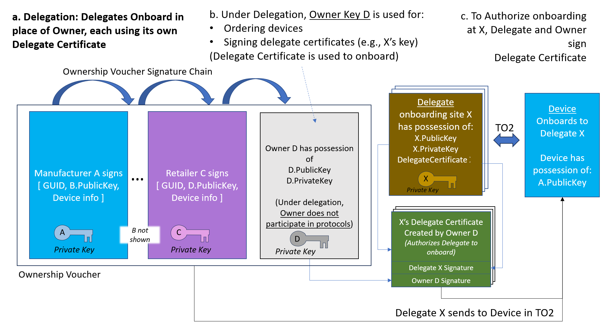
3.5.2. Delegate Mechanism ("Delegation")
The Delegate mechanism allows a (potentially enterprise-level) FDO Owner to authorize multiple sites for onboarding using a centralized mechanism.
The term "Delegate" is used herein as a convenient form of "Delegate Owner."
The Owner key is used for ordering equipment, and appears as the last key in the Ownership Voucher as always. Onboarding using the Owner key is still supported. In addition, one or many Delegate Certificates are created and distributed to onboarding sites across the enterprise. The Delegate Certificate, signed by the Owner, authorizes each Delegate to onboard based on that Owner’s key, without an extension of the Ownership Voucher.
The Delegate mechanism works by holding the Ownership Voucher constant and issuing Delegate Certificates in a static manner. If the Ownership Voucher is further extended, changing the Owner key, these Delegate Certificates no longer function.
Even if Delegation is normally used, the Owner key MAY still be used to onboard legacy devices or devices that do not choose to support Delegation. The usual restrictions of the Owner key apply in this case.
The Delegate Certificate is encoded in an X5CHAIN object in a protocol
field named DelegateChain. The X5CHAIN MAY
contain:
-
A single (leaf) certificate. This certificate identifies the Delegate, and is signed by the Owner directly, causing the authority of the FDO Owner to be conferred on the Delegate.
-
Two or more certificates. The Owner MUST sign the top (root) certificate in the chain, and each certificate signs the next (as is usual for certificate chain). The bottom (leaf) certificate identifies the Delegate. In this case, the Owner MAY permit other authorities to authorize Delegate(s).
The verification of the Delegate certificate(s) in the TO2 protocol MAY happen at any point, and in any order, so long as all certificates are verified before the first ServiceInfo (onboarding data) is processed.
A Delegate Certificate is used in the following messages:
-
Signing a
to1d(aka "Rendezvous Blob") inTO0.OwnerSignandTO1.RVRedirect -
Signing a
TO2.ProveOVHdr20message
When these messages include a Delegate Certificate, they are signed with the Delegate’s key in place of the Owner key. The Delegate Certificate, signed by the Owner, completes usual the chain of signatures in FDO onboarding.
Delegate certificates MUST be scoped to specify which operations the Owner
is permitting that Delegate to perform, through specification on permissions.
If a permission is not specified for a given operation requiring such an explicit
permission, a Delegate’s signature would NOT be a suitable substitute for an
Owner’s signature - and the given operation MUST fail with a DELEGATE_NOT_PERMITTED
error. Examples of this include:
-
Delegates MUST have
fdo-ekt-permit-redirectpermissions to run TO0 protocol -
Delegates MUST have one of the several
fdo-ekt-permit-onboard-permissions onboard an endpoint via TO2 -
Delegates MUST have
fdo-ekt-permit-onboard-reuse-credto instruct endpoint to use reuse protocol
Different Delegate Certificates MAY be used in the Rendezvous Blob and by the Owner, so long as the Delegate Certificate(s) authorize the same Owner key:
-
The delegated Owner role and Rendezvous Server roles MAY use different or the same Delegate Certificates
-
The Owner or Delegate MAY use a Delegate Certificate, while other does not use delegation (i.e., it has direct access to the Owner Key).
Each Delegate Owner SHOULD have an unique key. Each Delegate Owner MUST have a unique Delegate Certificate, that is signed by the Owner.
Delegate Certificates SHALL BE issued with unique Distinguished Names. Such names SHOULD be used to identify the Owner Onboarding Service.
Delegate Certificates and certificate chains are distinguished using X.509 key types specific to FDO (see § 3.5.5 Permissions & X.509 Extended Key Types). When used in FDO, these certificates and certificate chains MUST include at least one FDO Permission (key type) for a given operation. FDO Permissions MAY be specified in any certificate in the Delegate X5CHAIN. When FDO permissions are present in a given certificate, a subset of these permissions MUST be specified in certificates closer to the leaf (i.e., logically "below" this certificate). This makes it possible to to use a generic root CA certificate(s) for the "top" (root) of the chain, so long as FDO Permissions are present in certificates "lower" in the chain, or
In addition, best practices for X.509 Certificate Chain (X5CHAIN) validation apply. As applied to FDO usage these are:
-
Each certificate in a X5CHAIN MUST BE signed by the next certificate up until the trusted root certificate is reached.
-
The root of the Delegate chain MUST be signed by the final FDO Owner.
-
The leaf of the X5CHAIN MUST BE an end-entity certificate (i.e., not a CA certificate). This entity MUST serve the FDO TO2 protocol in the Owner role (aka Server role). There is one exception, see section § 3.5.2.1 Special case of CA Owner Key.
-
As per previous two items, it follows that an X5CHAIN containing a single certificate is signed by the FDO Owner and is also considered a "leaf" certificate.
-
All non-leaf certificates MUST set the "IsCA" flag. A Delegate certificate that is alone in the X5CHAIN MUST NOT set the "IsCA" flag.
-
Certificates SHOULD mark X.509 Extensions as "Critical", to prevent CAs who are unaware of the implications of granting a permission from unknowingly granting one.
A failure in the above validation SHALL be construed the same as if a signature validation of the Owner key has failed, and onboarding MUST NOT proceed.
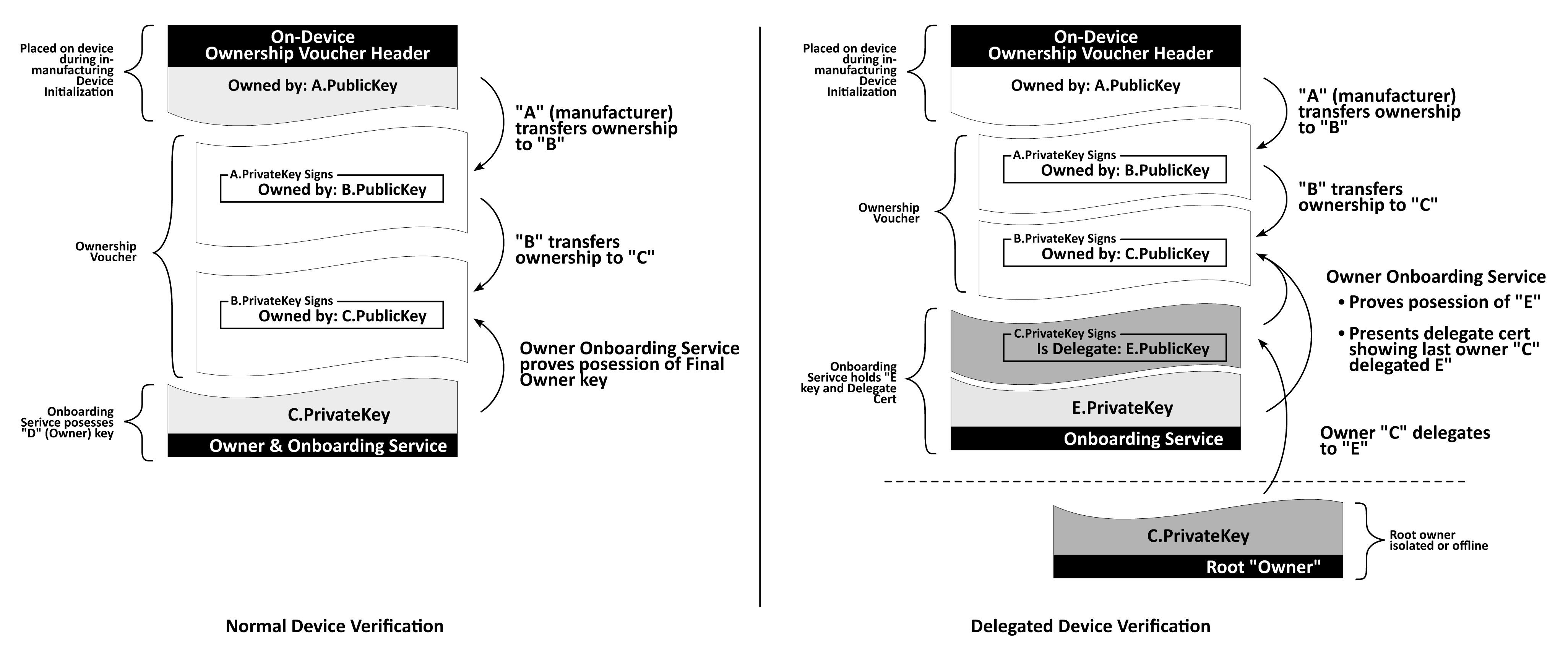
3.5.2.1. Special case of CA Owner Key
As stated above, a X5CHAIN (certificate chain) in the Ownership Voucher ends with a leaf certificate. There is one exception.
When Delegation is in use, the FDO Owner key MAY be a Certificate Authority (CA) key. Then Delegate Certificate(s) based on this CA are used to onboard.
Specifically, in this case:
-
The last entry in the Ownership Voucher has an X5CHAIN with only CA certificates in it. This Ownership Voucher MAY NOT be used for FDO onboarding, except using a Delegate Certificate.
-
Delegate Certificate(s) for onboarding MUST inherit from the CA Owner Key, and be signed by this key. The signature is as usual, since the Delegate Certificate is always signed by the Owner key, but in this case, the Delegate Certificate is a continuation of the Owner certificate chain.
-
Onboarding MAY ONLY take place based on the Delegate Certificate, signed by the Owner.
-
The Ownership Voucher MAY NOT be extended further.
-
The Delegate Certificate(s) MAY be registered with a Rendezvous Server.
This mechanism is intended to allow the Owner key to be managed by a 3rd party certificate vendor. By using a locally managed CA certificate in each Delegate, this mechanism gives a cost effective way to locally allocate and manage onboarding servers, while still using a 3rd party to protect the Owner key.
3.5.3. Rendezvous with Delegation
Delegation has an impact on the Rendezvous protocol (TO0 and TO1), because it is possible for a single Rendezvous transaction to yield to the Device multiple choices of potential Owner. When Delegation is in effect, the Device can process multiple Rendezvous records indicating the prospective Owner or Delegates. These records can include: a single (non-Delegate) FDO Owner and multiple Delegate Owners.
When Delegation is not enabled, either because it is not in use on the Owner’s site, or because the Device does not support Delegation (see § 3.3.3 CapabilityFlags), the Rendezvous server SHALL NOT return entries containing Delegate Certificates (i.e., it only returns the (non-Delegate) FDO Owner, as if there were no Delegate entries). In this situation, the Rendezvous protocol is similar to versions of FDO prior to version 2.0, and always returns zero or one Rendezvous entries for a candidate Owners. In this non-Delegate case, the RVPref field SHOULD be transmitted as Null and MUST NOT be interpreted by the Device.
The Rendezvous Server SHALL store Blobs received for a given GUID using the TO0 protocol, and serve these Blobs using the TO1 protocol:
-
Zero or one records indicating the prospective FDO Owner, without using Delegation.
-
Zero or more records indicating prospective Delegate Owners.
All FDO Rendezvous records have individual timeouts and MUST NOT be returned in a Rendezvous query after the timeout, within the precision of the Rendezvous Server’s timing mechanism (i.e., some time "slop" is permitted in the implementation).
Individual records SHALL be updated or replaced when the TO0 protocol affects them. For Delegate Blobs, the Rendezvous server SHALL maintain the IP address of the submitting party (Delegate Owner) in order to distinguish between records submitted by different prospective Delegates, so that the correct Rendezvous blob is updated.
In the TO1 protocol, the Rendezvous Server SHALL return Rendezvous Blob(s) to the requesting Device, consisting of:
-
Zero (0) or one (1) Rendezvous Records that do not use Delegation
-
Zero (0) or more Rendezvous Records that do use Delegation
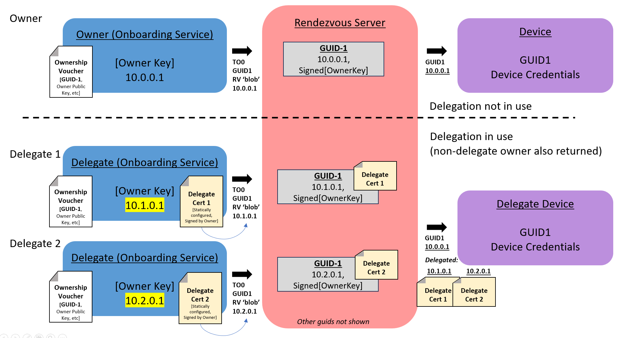
3.5.4. Rendezvous Weights
When Delegation is in effect, a given Rendezvous server MAY return multiple 'blob’s in the TO1 protocol. Each blob contains match rules, encoded in the RVTO2Addr field: RVPref. The match rules are used to generate weights for each entry, that creates a priority for interpreting these entries.
See § 3.3.16 RVTO2Addr (Addresses in Rendezvous 'blob') for additional information.
The match rules are supplied by the Rendezvous server based on local configuration information. This information is not transmitted in the TO0 protocol. Such information is outside the scope of this document.
Hosts that do not support the Delegate mechanism do not interpret RVTO2Addr...RVPref entries, but MUST be prepared to receive them in the Rendezvous protocol (i.e., if they are not "stripped off" by the Rendezvous server).
Match Rules
Match rules in each RVTO2Addr.RVPref are interpreted by the Device based on the DNS name (if known) or IP address(es) of the requesting Device.
Where the DNS name of the Device is known, DNS rules are processed against string DNS names whose suffix matches the suffix in the RVPref.RVPrefDNS entries. Otherwise, DNS rules are not processed by the Device.
All IP addresses that are explicitly given to the Device or are derived from resolving the DNS name are matched using the subnet matching of the RVPref.RVPrefIP rules.
Since the RVPref.RVPrefWeights is interpreted based on the presence of a match, the Device MAY stop at the first match and apply the weight:
RVPref.RVPrefWeights.RVWeightMatch.
Otherwise, the device SHOULD attempt all matches, before applying
RVPref.RVPrefWeights.RVWeightNoMatch.
A given Rendezvous entry can resolve to multiple IP addresses, and each SHOULD be attempted using the TO2 protocol. Then the next Rendezvous entry is attempted.
Since DNS entries for servers can resolve to many IP addresses, a given device MAY impose a limit on the number of IP addresses to be attempted for a given match. Obviously, hitting this limit must be interpreted as a failure to onboard, although a user interface can be used to distinguish this case, if one is available.
The device SHALL attempt to use Rendezvous information from greatest to least weight. Entries with Null weight SHALL NOT be used.
3.5.4.1. Examples of RVPref
The RVTO2Addr.RVPref field in the RendezvousInfo permits the configuration of the Rendezvous server to inform Devices about the priority of the various Delegate Owners.
3.5.4.1.1. Onboard Only to One Particular Site
If the site administrator wishes for Devices to onboard only to one appropriate Delegate Owner:
-
Set RVPref.RVPrefIP to match all IP addresses (e.g., subnet mask x.x.x.x/0)
-
Choose the highest weight (e.g., 1000) for this Delegate Owner.
3.5.4.1.2. Onboard to any Delegate Owner
If the site administrator wishes to allow a device to onboard to any appropriate Delegate Owner:
-
Set RVPref.RVPrefIP to match all IP addresses (e.g., subnet mask x.x.x.x/0)
-
Choose the same weight (e.g., 100) for all Delegate Owners.
3.5.4.1.3. Onboard to Local Site if up, else Global Site
The site administrator wishes for a device to onboard to the Delegate Owner on the same network segment if there is one and it is running, otherwise, to onboard to a "system default" Delegate Owner.
-
Set RVPref.RVPrefIP to match the local network. Choose a fixed weight (e.g., 100), but do not set a RVWeightNoMatch. Devices on the same IP network will match with the fixed weight, but Devices on another IP network will not match at all.
-
Create a Delegate Server with a lower weight (e.g., 10) that acts as the system "default".
If desired, a middle tier of "secondary" sites can be created with an intermediate weight (e.g., 50), to act as a "fallback" within segments of the network when the local site is down.
3.5.5. Permissions & X.509 Extended Key Types
X.509 Delegate Certificates SHALL be created with the following Extended Key Usage (EKU) OIDs, to denote the purpose and privileges associated with the certificate. One or more of the following EKUs SHALL be specified in any X.509 certificate being used as an FDO Delegate Certificate.
| FDO Permissions (PERM) | OID 1.3.6.1.4.1.45724.3.1.* |
| FDO Name Owner Match (NOM) | OID 1.3.6.1.4.1.45724.3.2 |
In the following table, PERM.x means the OID 1.3.6.1.4.1.45724.3.1.x.
| Identifier | PERM.x | Description |
|---|---|---|
fdo-ekt-permit-redirect
| PERM.1 | The signing Owner key authorizes the Delegate to
redirect via TO0/TO1. If this permission is not present, the
Delegate MAY NOT support the TO0/TO1 protocols, and an endpoint
SHALL terminate protocol with a DELEGATE_NOT_PERMITTED error.
|
fdo-ekt-permit-onboard-new-cred
| PERM.2 |
The signing Owner key authorizes the Delegate to
onboard a device (via TO2 protocol) and
provide new credentials after
onboarding with FDO TO2.
See section § 6 Resale Protocol.
Since only the Delegate knows the Owner-side credentials after TO2, the Owner site needs to provide a way to store and/or distribute these new credentials. This mechanism is outside the scope of this document. |
fdo-ekt-permit-onboard-reuse-cred
| PERM.3 | The signing Owner key authorizes the Delegate to onboard a device (via TO2 protocol) and set up credential reuse in the Device, as described in section § 7 Credential Reuse Protocol. |
fdo-ekt-permit-onboard-fdo-disable
| PERM.4 |
The signing Owner key authorizes the Delegate to
onboard a device (via TO2 protocol) and
disable the Device
from subsequent FDO by using DispDisable instead of providing
new Device credentials, as described in § 6.1 FDO Devices that Do Not Support Resale.
|
Any of the three fdo-ekt-permit-onboard- permissions are REQUIRED
for a Delegate to be able to onboard a device via TO2. If a Delegate
Certificate is presented to an endpoint during TO2 which does not
contain one of these permissions, endpoint MUST fail TO2 with a
DELEGATE_NOT_PERMITTED error.
If neither fdo-ekt-permit-new-cred nor fdo-ekt-permit-reuse-cred is
present, or if fdo-ekt-permit-fdo-disable is present:
further use of FDO on this device MUST be disabled after a
successful onboard.
The following table describes the Extended Key Usage (EKU) OIDs for the FDO Name-Owner Match (NOM) mechanism. The NOM mechanism extends FDO sites supporting Delegation to allow identified by certificate instead of by key.
| Identifier | OID | Description |
|---|---|---|
fdo-ekt-NOM
| 1.3.6.1.4.1.45724.3.2 | Used to specify the
NOM (Owner Name) that apply to this certifiate.
See § 3.5.6 Name-Owner Match (NOM) and NOM Constraint Identifiers.
|
fdo-ekt-NOM-constraint
| 1.3.6.1.4.1.45724.3.3 | Used to specify a comma-separated list of
NOM (Name-Owner Matches) that a CA may issue certificates for.
See § 3.5.6 Name-Owner Match (NOM) and NOM Constraint Identifiers.
|
Proper expression of permissions in Delegate Chains require any permission to be specified in all certificates in the chain. The lack of a permission in any certificate within the chain in itself is not invalid, but it means that for the sake of any permissions validation, this permission is NOT being granted by this chain.
3.5.6. Name-Owner Match (NOM) and NOM Constraint Identifiers
3.5.6.1. Overview
FDO usually extends ownership to new owners by expressing the cryptographic public key held by that owner within an ownership voucher. However, there are times when the new owner’s public key may not be readily known, or when key management is dynamic and handled by third-party CA services that may revoke, re-issue, or provision certificates to different entities. In these situations, the NOM mechanism offers a valuable alternative.
As an optional and alternate mechanism to key-based identity, Delegate Certificates and Ownership Extensions can extend the concept of FDO Identity using two distinct X.509 Extensions:
-
Name-Owner Match (NOM): This identifies the single name of the owner associated with the certificate.
-
Name-Owner Match Constraint (NOM Constraint): This is used by a Certificate Authority (CA) to define naming constraints for certificates it issues, potentially as a list of allowed names or name patterns.
These extensions, each identified by a specific Object Identifier (OID) (defined in a later section), establish bindings between specific "names" and the identity of FDO Delegate Owners or the next FDO Owner, or restrict the names that descendant certificates may claim. The primary purpose of these NOM-related extensions is to allow FDO certificates to be issued based on flexible naming conventions while maintaining a clear and hierarchical scoping model, complementing traditional key-based ownership conveyance.
3.5.6.2. NOM and NOM Constraint Extension Structures and Semantics
NOM and NOM Constraint extensions SHALL be included within FDO-related X.509 Certificates (Delegate Certificates or Ownership Extensions) as X.509 Extensions, when the NOM mechanism is utilized.
3.5.6.2.1. NOM Extension Format
The NOM extension SHALL contain a single string identifying the owner associated with the certificate via a name. This string SHALL conform to one of the following formats:
-
Unique Identifier: A string representing a uniquely identifying name chosen by the issuing CA.
-
Exact Name: A multi-parted name (e.g.,
a.example.com).
The NOM extension SHALL NOT contain entries prefixed with a leading dot ..
3.5.6.2.2. NOM Constraint Extension Format
The NOM Constraint extension SHALL contain a comma-separated list of entries. Each entry SHALL conform to one of the following formats:
-
Unique Identifier: A string representing a uniquely identifying name chosen by the issuing CA.
-
Suffix Match: A string representing the suffix of a multi-parted name, prefixed with a dot
.character (e.g.,.example.com). This format indicates a match for any name ending with the specified suffix. -
Exact Name: A multi-parted name (e.g.,
a.example.com).
The uniqueness of any "Unique Identifier" chosen by the issuing CA SHALL be granted by the issuing CA within the scope of names it issues.
3.5.6.2.3. Grantee Specification
A NOM extension in a certificate defines the single name of the owner it identifies. A NOM Constraint extension in a CA certificate specifies the set of names that descendant certificates issued by that CA MAY claim in their own NOM extensions or further constrain in their NOM Constraint extensions.
A certificate containing a NOM extension, whose identified owner’s name matches a corresponding NOM Constraint from an ancestor CA, SHALL grant permissions, including but not limited to onboarding and ownership extension, to the identified entity. This is provided that the certificate:
-
Contains a NOM whose single value matches a permitted naming rule from an ancestor’s NOM Constraint.
-
Was signed by the CA authorized to issue certificates for that name space.
3.5.6.2.4. Uniqueness Constraint
The combination of any name specified in a NOM or any entry in a NOM Constraint extension and the issuing CA SHALL be globally unique.
3.5.6.2.5. Extension and Conformance in Certificate Chains
Within a certificate chain:
-
A NOM Constraint extension from a parent CA MAY be replicated or further constrained by a descendant CA. When extending, descendant constraints SHALL be accomplished by appending sub-names (e.g., DNS name elements) to the left of an existing NOM Constraint entry from the parent. A given NOM Constraint entry MAY be extended multiple times down the chain.
-
When a NOM Constraint is replicated or extended by a descendant certificate, the scope of the descendant’s NOM Constraint SHALL be equal to or narrower than that of its parent; it SHALL NOT expand the scope defined by any ancestor in the chain.
-
A NOM Constraint constrains the NOMs or further NOM Constraints in the immediate descendant certificate. Conversely, a NOM or NOM Constraint in a descendant certificate is constrained by the NOM Constraint found in its immediate parent certificate.
-
If a CA certificate includes a NOM Constraint extension, it indicates that subsequent FDO identity within that branch of the certificate chain SHALL be managed via the NOM mechanism. Therefore, any certificate directly issued by such a CA that is intended for FDO ownership transfer or delegation SHALL contain either a NOM (if it is a leaf certificate representing a final owner) or a NOM Constraint (if it is an intermediate CA further delegating permissions). The names specified in these descendant NOM or NOM Constraint extensions SHALL conform to the parent’s NOM Constraint.
-
Conversely, if a CA certificate does not include a NOM Constraint extension, it implies that FDO ownership or delegation authority for that specific link in the chain is conveyed primarily via cryptographic keys. In such instances, descendant certificates are not directly constrained by that ancestor via the NOM mechanism; however, they SHALL still adhere to any NOM Constraints imposed by higher ancestors in the chain if such constraints exist.
-
The owner’s name, as specified in a certificate’s NOM (its self-identifying single name), SHALL conform to all applicable NOM Constraints present in its ancestor certificates in the chain. If a certificate’s NOM does not fall within the constraints of an ancestor, the certificate SHALL be considered invalid for FDO purposes.
3.5.6.2.6. Certificate Type Specificity
-
Leaf Certificates (i.e., a single X.509 certificate with no further subordinates) SHALL contain a NOM extension to identify their associated owner with a single name, when the NOM mechanism is utilized for identity in that part of the certificate chain. They SHALL NOT specify wildcard elements in their NOM extension. Leaf certificates SHALL NOT contain a NOM Constraint extension, as they do not issue further certificates.
-
Intermediate and Root CA Certificates MAY contain a NOM extension to identify their associated owner with a single name. An intermediate certificate that is intended only for issuing further certificates (i.e., solely acting as a CA for FDO ownership transfer and not as a leaf owner itself) is not required to contain a NOM extension. In either case (whether containing a NOM or not), the intermediate’s NOM (if present) and/or its NOM Constraint SHALL still be constrained by any applicable NOM Constraints from its parent certificates in the chain. These certificates MAY also contain a NOM Constraint extension to define the naming scope for certificates they are authorized to issue. Root or intermediate certificates MAY employ wildcard suffixes (e.g.,
.example.com) in their NOM Constraint to scope the range of certificates they are authorized to issue.
3.5.6.3. Discussion on Naming Models (Non-Normative)
To explicitly differentiate FDO-specific certificate usage from generic X.509 applications (e.g., standard web TLS or S/MIME), NOM and NOM Constraint extensions use distinct Object Identifiers (OIDs) and operate within a unique FDO interpretation context. This dual distinction prevents FDO certificates from being misinterpreted for non-FDO purposes, and equally prevents non-FDO certificates from being misconstrued as conveying FDO permissions or properties simply by containing an FDO-defined extension.
The multi-parted naming model used in both NOM and NOM Constraint extensions is compatible with DNS names, domains, and subdomain syntax. This allows many CAs to leverage DNS names as a robust mechanism to assure global uniqueness and ownership.
However, not all CAs might prefer or be able to utilize DNS names. For instance, private CAs might not possess knowledge or control over the DNS hierarchy of their certificate recipients. Furthermore, a distinct one-to-one mapping between organizations or sub-organizations receiving such certificates and their corresponding DNS names might not always exist.
Therefore, while DNS-based organizations are valid, permitted, and well understood, the only strict constraint on a "name" is the issuing CA’s grant of its uniqueness among other names it issues. Alternative examples for unique names could include:
-
An organization’s internal identifier.
-
A customer account number.
The fundamental principle is that the CA must ensure its chosen naming scheme uniquely identifies an owner within the scope of certificates it issues.
3.5.6.4. Example Name Constrints (Non-Normative)
NOTE: The following example illustrates the use of NOM and NOM Constraint extensions within a certificate chain, showing how an intermediate CA can have its owner identified by a NOM while also constraining names for its own descendants (NOM Constraint):
| Delegate Cert | Example text | Comment |
|---|---|---|
| Root CA | .example.com
| Wildcard, suffix of DNS name |
| Intermediate CA | .site1.example.com
| Extend wildcard to left |
| Leaf | hostA.site1.example.com
| Domain name based on wildcard |
hostB.site1.example.com
| 2nd Domain name in leaf |
3.5.6.5. Example Certificate Chain with NOM and NOM Constraint (Non-Normative)
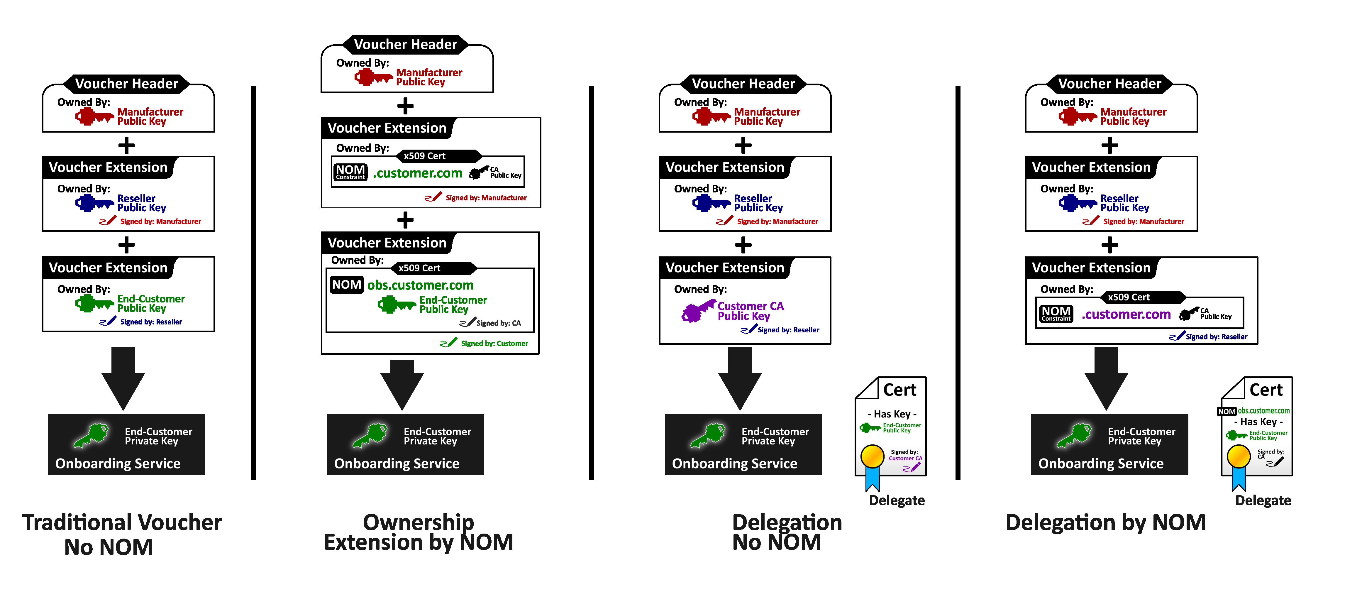
3.6. Device Attestation Sub Protocol
The Device Attestation signature is used by the FDO Device to prove its authenticity to the FDO Rendezvous and the FDO Owner. Device attestations conform to the EAT specification [EAT].
The EAT token structure is reflected in EATokenBase.
The protected and payload sections are defined for each signature use,
using the socket/plug mechanism with the variables
$EATProtectedHeaders and $EATPayloads.
EAT attestations can be very extensive and can contain private or otherwise sensitive items. For purposes of FDO, the attestation SHOULD be simplified to contain non-linkable items to the extent possible. In particular, the FDO GUID MUST appear as the EAT UEID. Since this GUID is replaced at the successful conclusion of the TO2 protocol, it cannot be used to link future transactions.
A given Device might wish to generate a more complete EAT attestation when running over an encrypted channel. This EAT token can be transmitted using ServiceInfo. The token can be generated using a nonce from an earlier ServiceInfo message to prove freshness.
In some cases, an entity attestation signature cannot stand alone, but requires some protocol interaction to prepare for it. Examples:
-
a multi-application Restricted Operating Environment (ROE) can negotiate program instance parameters with the verifier before the signature can be trusted.
-
revocation information for a signature is sometimes obtained in-band in a protocol, permitting the signing entity to have a single communications link with the verifying entity.
FDO maintains an embedded signing protocol for the Device, with the message:
-
eSig — from Device to verifier, contains the actual signature, following the EAT specification.
Note: the eA and eB fields used in previous versions of FDO were used with the EPID signing mechanism. Since EPID is removed from this version of FDO, we have removed eA and eB as well.
There are two uses of this protocol in FDO.
In the TO1 protocol:
-
eSig is TO1.ProveToRV
In the TO2 protocol:
-
eSig is TO2.ProveDevice
See definition of SigInfo (§ 3.3.5 SigInfo)
3.6.1. ECDSA secp256r1 and ECDSA secp384r1 Signatures
ECDSA signature attestation is defined in accordance with [RFC9053] and [EAT].
ECDSA secp256r1 uses SHA256 hash, and ECDSA secp384r1 uses SHA384 hash.
For ECDSA, both the private key and the public key are Device identities. This means that the FDO Rendezvous Server and FDO Owner who verify the Device attestation signature receive a unique and permanent identity for the device, even before they verify the signature. This information can be used to trace the subsequent owners of the device. For this reason, we recommend careful administrative measures to ensure that this information is used securely and discarded appropriately.
3.7. Key Exchange in the TO2 Protocol
The FDO TO2 Protocol requires message-level encryption. The TO2 Protocol transmits potentially long-term credentials to the Device, and these credentials are confidential between the Device ROE and its new Owner.
Key exchange is used in FDO to allow the Device and its Owner to agree on shared secrets.
Where authenticated encryption is used, a single SEVK (Session Encryption and Verification Key) is the shared secret, used both to encrypt and verify the payload.
For legacy encryption, a Session Verification Key (SVK) is used to perform a HMAC over each message to ensure message integrity. A Session Encryption Key (SEK) is used to encipher each message to ensure message confidentiality.
Key Exchange starts with a protocol to construct a shared secret between the Owner and the Device. This is accomplished using one of supported methods below, chosen by the device. Next, the Device and Owner each uses an identical Key Derivation Function on the shared secrets to compute the session keys, either SEVK or SVK and SEK.
When Delegation is enabled, the Delegate takes the part of the Owner and the Delegate key is used instead of the Owner key.
The selection of a key exchange algorithm is denoted in the TO2.ProveDevice20.kexSuiteName
variable. Key exchange algorithms are presented for Owner key RSA and
Owner key ECDSA.
CDDL
KexSuitNames /= (
    "DHKEXid14",
    "DHKEXid15",
    "ASYMKEX2048",
    "ASYMKEX3072",
    "ECDH256",
    "ECDH384"
)
KexSuiteNames = KexSuitNames # correct typo from earlier versions.
When the Owner Key is RSA:
-
“DHKEXid14”: Diffie-Hellman key exchange method using a standard Diffie-Hellman mechanism with a standard NIST exponent and 2048-bit modulus ([RFC3526], id 14). This is the preferred method for RSA2048RESTR Owner keys.
-
“DHKEXid15”: Diffie-Hellman key exchange method using a standard Diffie-Hellman mechanism with a standard National Institute of Standards and Technology (NIST) exponent and 3072-bit modulus. ([RFC3526], id 15), This is the preferred method for RSA 3072-bit Owner keys.
-
“ASYMKEX2048”: Asymmetric key exchange method uses the encryption by an Owner key based on RSA2048RESTR; this method is useful in FDO Client environments where Diffie-Hellman computation is slow or difficult to code.
-
“ASYMKEX3072”: The Asymmetric key exchange method uses the encryption by an Owner key based on RSA with 3072-bit key.
DHKEXid14 and DHKEXid15 differ in the size of the Diffie-Hellman modulus, which is chosen to match the RSA key size in use.
When the Owner key is ECDSA:
-
“ECDH256”: The ECDH method uses a standard Diffie-Hellman mechanism for ECDSA keys. The ECC keys follow NIST P-256 (SECP256R1)
-
“ECDH384”: Standard Diffie-Hellman mechanism ECC NIST P-384 (SECP384R1)
The choice of key exchange algorithm follows the cryptography of the Owner key. See § 3.7.5 Mapping of Key Exchange Protocol to FDO Crypto Options.
Subsequent messages are protected for confidentiality and integrity:
-
Using an authenticated encryption mechanism, supported by COSE [RFC9053]. SEVK is used for this single mechanism.
-
Using a legacy Encrypt-then-Mac combination of COSE primitives SEK is used for encryption and SVK is used for integrity protection. AES-CBC or AES-CTR mode are used, as defined in [SP800-38A].
Sizes for SVK, SEK and exemplary sizes for specific cases of SEVK in FDO are given in the following tables.
Table ‑. Exemplary SEVK Sizes (authenticated encryption)
| Confidentiality & Integrity | SEVK |
|---|---|
|
A128GCM AES-CCM-16-128-128 | 128 bits |
|
A256GCM AES-CCM-16-128-256 | 256 bits |
Table ‑. SEK and SVK Sizes (encrypt-then-MAC)
| Confidentiality | Integrity | SEK | SVK |
|---|---|---|---|
|
AES-CTR-128 AES-CBC-128 | HMAC-SHA256 | 128 bits | 256 bits |
|
AES-CTR-256 AES-CBC-256 | HMAC-SHA384 | 256 bits | 512 bits |
The key exchange protocols below yield a shared secret, ShSe and a
ContextRand bitstring. These are used as input to the KDF function
defined in § 3.7.4 Key Derivation Function.
3.7.1. Diffie-Hellman Key Exchange Protocol
The following steps describe the Diffie-Hellman key exchange protocol (DHKEXid15), as part of the verification of the Ownership Voucher:
-
The Device and Owner each choose random numbers (Owner: a, Device: b), and encode these numbers into exchanged parameters A and B:
A = g^a mod p
B = g^b mod pThe values “p” and “g” are chosen from [RFC3526], with sizes as follows:
| kexSuiteName | Modulus (p) size | Generator (g) size | a & b size |
|---|---|---|---|
| DHKEXid14 | 2048 | 2 | 256 bits |
| DHKEXid15 | 3072 | 2 | 768 bits |
-
The Device sends A to the Owner as parameter
TO2.ProveDevice20.xaKeyExchange. Note that this parameter is signed by the Device Attestation key. -
The Owner sends B to the Device as parameter TO2.ProveDevice.xBKeyExchange. This parameter is signed with the Owner key from the Ownership Voucher, which is proved as trusted later in the TO2 Protocol, but before the key exchange is used. When Delegation is enabled, this parameter is signed by the Delegate key.
-
The Owner computes shared secret:
ShSe = (A^b) mod p -
The Device computes shared secret:
ShSe = (B^a) mod p
The ContextRand bitstring is null ('').
3.7.2. Asymmetric Key Exchange Protocol
The following steps describe the Asymmetric key exchange protocol (ASYMKEX2048 or ASYMKEX3072), as part of the verification of the Ownership Voucher. Asymmetric key exchange applies only to devices that support an RSA-based Ownership Voucher. Sizes are as follows:
| Owner & Device Randoms | MGF Hash Function | |
|---|---|---|
| ASYMKEX2048 | 256 bits each | SHA256 |
| ASYMKEX3072 | 768 bits each | SHA256 (larger hash size not needed for ASYMKEX3072) |
-
Owner allocates a random value called the Owner Random. Owner sends the Owner Random to the Device as
TO2.ProveOVHdr20.xbKeyExchange. This value is signed with the Owner key, but is not encrypted. -
Device allocates a random value called the Device Random. Device encrypts the Device Random with the Owner public key using RSA encrypt using Optimal Asymmetric Encryption Padding (OAEP) with Mask Generation Function (MGF) SHA256. The RSA key is stored in the TO2.ProveOVHdr20.CUPHOwnerPubKey and in last entry of the Ownership Voucher. Either source can be used.
-
The encrypted Device Random is sent to the Owner as
TO2.ProveDevice.xBKeyExchangeThis parameter is signed with the Device attestation key. -
Owner decrypts TO2.ProveDevice.xBKeyExchange using its Owner Private Key (the same private key it used to sign in the TO2.ProveOVHdr20 message). Note that the Owner Private Key must be RSA-based.
-
The Owner & Device each compute shared secret
ShSe = DeviceRandom
ContextRand = OwnerRandom
3.7.3. ECDH Key Exchange Protocol
The following steps describe the ECDH key exchange protocol (ECDH), as part of the verification of the Ownership Voucher. ECDH applies only to devices that support an ECDSA-based Ownership Voucher.
Curve and Random parameters are as follows:
| kexSuiteName | ECC Curve | Owner & Device Randoms |
|---|---|---|
| ECDH256 | NIST P-256 (Gx, Gy), p each 256 bits | 128 bits |
| ECDH384 | NIST P-384 (Gx, Gy), p each 384 bits | 384 bits |
Curve parameters are taken from NIST P-series as above, including p and the base point (Gx, Gy).
ECC curves allocated for key exchange must be used once only.
blen(x) describes the length of the of the input (x) as a 16-bit unsigned integer (uint16).
-
The Device and Owner each choose random numbers (Owner: a, Device: b), and encode these numbers into exchanged parameters A = ((Gx, Gy) * a) mod p, and B = ((Gx, Gy) * b) mod p. A and B are points, and have components (Ax, Ay) and (Bx, By), respectively, with bit lengths same as (Gx, Gy).
-
The Device and Owner each choose a random number (as per table above), to be supplied with their public keys, respectively DeviceRandom, and OwnerRandom.
-
The Owner sends
TO2.ProveOVHdr20...xAKeyExchangeto the Device as the bstr:blen(Ax) || Ax || blen(Ay) || Ay || blen(OwnerRandom) || OwnerRandom
Note that this parameter is signed by the Owner key from the Ownership Voucher, which is proved as trusted later in the TO2 Protocol, but before the key exchange completes.
-
The Device sends
TO2.ProveDevice...xBKeyExchangeto the Owner as the bstr:blen(Bx) || Bx || blen(By) || By || blen(DeviceRandom) || DeviceRandom
This parameter is signed with the device attestation key.
-
The Owner computes shared secret Sh = (B*a mod p), with components (Shx, Shy). The Device computes shared secret Sh = (A*b mod p), with components (Shx, Shy). The shared secret ShSe is formed as:
ShSe = Shx || DeviceRandom || OwnerRandom
ContextRand is null ('')(Note that Shy is not used to construct ShSe).
-
The DeviceRandom and OwnerRandom values are used to increase the entropy in the generated keys, in order to reduce the possibility of certain related key weaknesses.
-
The lengths of a, b, DeviceRandom and OwnerRandom are chosen to permit the shared secret to source SVK & SEK of appropriate lengths.
-
In steps 3 and 4, the values of A, B, DeviceRandom and OwnerRandom are transmitted within a single bstr as length-preceding binary strings (i.e., the contents of the string is not CBOR).
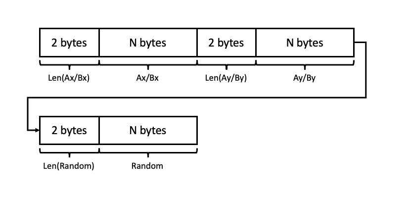
Note: This mechanism is intended to be a standard implementation of NIST ECC P-256 or P-384, compatible with other software and hardware implementations.
Note: Shy is not used to compute the shared secret ShSe, because it can be derived from Shx and the curve equation. Hence it provides no additional entropy.
3.7.4. Key Derivation Function
Owner and Device both have shared secret ShSe and a ContextRand bitstring, computed by one of the above key
exchange protocols. These values are fed into the Key Derivation
Function defined in [SP800-108r1-upd1], KDF in Counter Mode,
section 5.1, as follows:
(Notation)
-
"
text" indicates the UTF-8 codes for the 4-character string text with no given length and no trailing zero. For the strings in question, the UTF8 values also match ASCII. -
(byte)nindicates a single byte with contents n.
The following refers directly to variables defined in [SP800-108r1-upd1]:
-
The number of bits of derived keying material, L, is the number of bits of KDF output required.
For authenticated encryption modes (SEVK needed), this is the bit length of SEVK required for the selected encryption algorithm.
For Encrypt-then-MAC (SVK and SEK needed), L is the number of bits in the required SVK plus the number of bits in the SEK.
L is a 16 bit number, expressed in big-endian format.
-
The PRF (pseudo-random function) is either HMAC-SHA256 or HMAC-SHA384, as given in the description of the cipher suite, see § 4.4 Encrypted Message Body. The PRF key, KI, is shown as the first argument in [SP800-108r1-upd1]. For clarity, we denote the HMAC function as:
HMAC-SHAnnn<hmac-key>(hmac-text) -
The Key Derivation Key (KI), is
ShSe. -
The Label is the string: "
FIDO-KDF" -
The Context is the concatenation of: "
AutomaticOnboardTunnel" andContextRand, defined in the key exchange. -
The counter for each iteration, i, is a single byte (i.e., r = 1).
When both SVK and SEK are required, the KDF is run until there are enough bits for both SVK and SEK, and an output buffer, result, has the K(i) bitwise concatenated. Then the result buffer is interpreted as:
SVK || SEK || extrabits
where extrabits consists of any extra bits beyond the length of
SVK||SEK, and is discarded.
When SEVK is required, the KDF is run until there are enough bits for SEVK, and an output buffer, result, has the K(i) bitwise concatenated. Then the result buffer is interpreted as:
SEVK || extrabits
and extrabits is discarded, as above.
As an example, the KDF loop when using SHA256 to compute 128 bits of key material as SEVK is as follows (assume the "For" loop executes one iteration in this pseudo-code):
result(0) := Ø
For i = 1 to 1, do
    a. Context := ("AutomaticOnboardTunnel"||ContextRand)
    b. Lstr := (byte)0||(byte)128
    c. K(i) := HMAC-SHA256<ShSe>((byte)i||"FIDO-KDF"||(byte)0||Context||Lstr)
    d. result(i) := result(i-1) || K(i)
Then SEVK = K(1) >> 128 (i.e., the leftmost 128 bits of K(1), and extrabits is the remaining 128 bits of K(1).
3.7.5. Mapping of Key Exchange Protocol to FDO Crypto Options
The following table shows the valid choices for key exchange protocol based on choice of device attestation and owner attestation algorithms selected by the device manufacturer. The key exchange method MAY be configured in the device at the time of manufacturing and not dynamically selected during TO2 protocol.
The choice of cryptography for the key exchange protocol follows the cryptography in the Ownership Voucher (Owner key, and other keys in the Ownership Voucher). Where the Device key and Owner key use different cryptography, the Device and Owner might need to support additional algorithms to allow verification and key exchange. We encourage a choice that limits the software or hardware required in the Device.
When Delegation is enabled, the Owner key refers to the Delegate key.
Table ‑. Key Exchange and FDO Crypto Mapping
| Device Attestation | Owner Attestation | Key Exchange |
|---|---|---|
| ECDSA NIST P-256 | RSA2048 or RSA2048RESTR | DHKEXid14/ASYMKEX2048 (crypto mismatch) |
| ECDSA NIST P-384 | RSA2048 or RSA2048RESTR | DHKEXid14/ASYMKEX2048 (crypto mismatch) |
| ECDSA NIST P-256 | RSA3072 | DHKEXid15/ASYMKEX3072 |
| ECDSA NIST P-384 | RSA3072 | DHKEXid15/ASYMKEX3072 (crypto mismatch) |
| ECDSA NIST P-256 | ECDSA NIST P-256 | ECDH256 |
| ECDSA NIST P-384 | ECDSA NIST P-256 | ECDH256 (crypto mismatch) * |
| ECDSA NIST P-256 | ECDSA NIST P-384 | ECDH384 (crypto mismatch) |
| ECDSA NIST P-384 | ECDSA NIST P-384 | ECDH384 |
Note: Concerning "crypto mismatch" comments, above. The Ownership Voucher and the Device key in these configurations have different cryptographic strengths. These are legal configurations, and the overall evaluation of the protocol strength is based on the weaker of the two.
3.8. RendezvousInfo
The RendezvousInfo type indicates the manner and order in which the Device and Owner find the Rendezvous Server. It is configured during manufacturing (e.g., at an ODM), so the manufacturing entity has the choice of which Rendezvous Server(s) to use and how to access it or them.
Note: At the successful completion of the TO2 protocol, the Owner RendezvousInfo replaces the previous RendezvousInfo. This mechanism can also be used to change the RendezvousInfo in the supply chain.
RendezvousInfo consists of a sequence of instructions which are interpreted in order during the TO0 and TO1 Protocols. These "rendezvous instructions" are themselves grouped together in a sub-sequence.
Each set of rendezvous instructions is
interpreted as one way to reach the Rendezvous Server, using different paths or with
differing conditions. For example, one set might indicate using the wireless
interface, and another set might indicate using the wired
interface; or one set might use a DNS .local address, while another
uses a global DNS address that the manufacturer provides across the Internet.
The Owner and Device process the RendezvousInfo, attempting to access the Rendezvous Server while they do so. The first successful connection is used. When Delegation is in effect, the Delegate takes on the role of the Owner.
It is possible that a given instruction set corresponds to multiple ways to access the Rendezvous Server (e.g., multiple IP addresses that correspond to a single DNS name), and these must all be tried before the Device or Owner moves to the next element of the sequence. This can be thought of as a re-writing rule, where the DNS expands one rule for DNS into one rule for each IP address resolved by the DNS.
The Device SHOULD process all DNS entries returned for a given DNS name. These are tried in any order, or MAY be tried in parallel. An implementation limit MAY be set for DNS entries that return a vast number of IP addresses, such as Internet service sites.
The Device and Owner MAY avoid obviously redundant operations, such as contacting the same IP address twice, once via DNS name and once via explicit IP address.
Conceptually, to execute each rendezvous instruction, the program defines a set of variables, one for each tag in the RendezvousInfo instructions. It initializes all variables to default values. Then the rendezvous instruction is interpreted, and updates each variable. If the user input variable is set to true, and user input is available, the user is allowed to update each variable. On constrained devices, some variables do not exist. The constrained implementation interprets each instruction as if this variable was not present.
Some variables apply only to the Owner and some only to the Device. See the table below. When a variable does not apply, it is interpreted as if it had never been specified. This means that the Owner can only ever notice the tags: RVOwnerOnly, RVIPAddress, RVOwnerPort, and RVDns. This is because the Owner, as a cloud-based server, is expected to use normal Internet rules to access the Rendezvous Server. The Device, which might be in a specialized network and might be constrained, might need additional parameters.
The RVDevOnly, RVOwnerOnly and RVDelaySec tags have side effects.
-
When [RVDevOnly] appears in a set of instructions, an Owner (or Delegate) must skip the entire set
-
When [RVOwnerOnly] appears in a set of instructions, a Device must skip the entire set
-
When [RVDelaysec, uint32] appears in a set of instructions, the set is followed by a delay for the number of seconds specified, increased or decreased by a random value of up to 25% of the specified time.
It is assumed that an instruction containing RVDelaysec with a default value is appended to the end of the RendezvousInfo to force a particular randomized delay before retrying the entire sequence. An explicit instruction of this form overrides the default value.
$RVVariable /= (
    RVDevOnly     => 0,
    RVOwnerOnly   => 1,
    RVIPAddress   => 2,
    RVDevPort     => 3,
    RVOwnerPort   => 4,
    RVDns         => 5,
    RVSvCertHash  => 6,
    RVClCertHash  => 7,
    RVUserInput   => 8,
    RVWifiSsid    => 9,
    RVWifiPw      => 10,
    RVMedium      => 11,
    RVProtocol    => 12,
    RVDelaysec    => 13,
    RVBypass      => 14,
    RVExtRV       => 15
)
RVProtocolValue /= (
    RVProtRest    => 0,
    RVProtHttp    => 1,
    RVProtHttps   => 2,
    RVProtTcp     => 3,
    RVProtTls     => 4,
    RVProtCoapTcp => 5,
    RVProtCoapUdp => 6
);
$RVMediumValue /= (
)
Note about Wi‑Fi security.
The RVWifiSsid parameter is set in manufacturing. This is one way for a manufacturer to specify a purposely provisioned Wi‑Fi "onboarding network". For example, a device could be provisioned with RVWiFiSsid="FDO". Then a user can provision such a SSID-based network when the device onboards. If the user has a stateful inspection firewall, it is possible to leave the onboarding segment up for continued FDO use, by restricting it only to run the FDO protocol (which the user has already decided to trust).
If the manufacturer includes a RVWifiPw, there is no improvement in security. An attacker only has to look up the manufacturer’s information to find out the password. The password therefore has no function for authentication in this case. It can be a convenience, however. Some personal consumer devices look for "open" Wifi connections and automatically connect to them. Since an onboarding segment is only usable for FDO, human users would be inconvenienced to attach automatically to the segment. The password serves the purpose of keeping them from automatically connecting.
Note: Recent developments in specifications associated with Wi‑Fi networks,
such as OpenRoaming, offer better solutions for vendor products with
FDO. Please see:
OpenRoaming for IoT — FIDO Device Onboard Framework from the Wireless
Broadband Alliance
https://wballiance.com/openroaming-for-iot-fido-device-onboard-framework/
Table ‑. RendezvousInfo Variables
| Rendezvous Instruction Variable | Default Value | Variable Encoding Tag | Variable Type | Device/Owner |
|---|---|---|---|---|
| Device Only | None | RVDevOnly | none | Both |
| Owner Only | None | RVOwnerOnly | none | Both |
| IP address | None | RVIPAddress | IPAddress | Both |
| DNS name | None | RVDns | DNSAddress | Both |
| Port, Device | Based on protocol | RVDevPort | uint16 | Device |
| Port, Owner | Based on protocol | RVOwnerPort | uint16 | Owner |
| TLS Server cert hash | None | RVSvCertHash | Hash | Device |
| TLS CA cert hash | None | RVClCertHash | Hash | Device |
| User input | No | RVUserInput | bool | Device |
| SSID | None | RVWifiSsid | tstr | Device |
| Wireless Password | None | RVWifiPw | tstr | Device |
| Medium | Device dependent | RVMedium | $RVMediumValue(uint8) | Device |
| Protocol | TLS | RVProtocol | RVProtocolValue(uint8) | Device |
| Delay | 0 | RVDelaysec | uint32 | Both |
| Bypass | none | RVBypass | none | Device |
| External RV | none | RVExtRV | array | Device |
All the above fields of RendezvousInfo are optional, except as follows:
-
One of RVIPAddress or RVDns MUST be present. If both are present, RVDns is processed first, then RVIPAddress is used as an additional address (if it was not already returned by the DNS query).
-
RVDelaysec is implicitly included if not present.
Rendezvous Instruction (RendezvousInstr) entries are specified as having the variables in alphabetical order. This does not affect the interpretation of these variables, but makes the computation of a signature that includes them simpler for some implementations.
The following list indicates how each rendezvous instruction is interpreted, where one variable exists per attribute.
-
If the RVDevOnly element appears on the Owner, this instruction is terminated and control proceeds with the next set of instructions.
-
If the RVOwnerOnly element appears on the Device, this instruction is terminated and control proceeds with the next set of instructions.
-
The Medium is selected. The Device uses the selected preferred medium (RVMedium), or terminates this instruction. When no medium is specified, the Device can establish its own preference, perhaps based on the other parameters (for example, TLS might be available on one medium, but not another). If a selected medium does not apply (e.g., Wi‑Fi where there is no Wi‑Fi interface), control proceeds with the next set of instructions.
-
On the Device, the protocol is chosen (RVProtocol), if it is supported. Otherwise, the instruction terminates. The Owner always chooses the protocol “https”.
-
The Device attempts to resolve the DNS address. If DNS query is successful, then the resolved IP addresses are tried one after another, as if this rule where rewritten with one IP address per DNS resolved value. In this operation, an explicit IP address is processed just after all DNS resolutions.
-
Else, if DNS resolution fails or the Device fails to communicate with all of the resolved IP addresses, then the specified IP address is used as the target IP address.
-
Else, if there is no specified IP address, the instruction terminates.
-
If TLS is used on a Device (RVProtocol=https or RVProtocol=tls), the hash instructions are used as specified against server certificates appearing in the TLS handshake. This applies to the Device only.
-
If the server certificate hash is specified (on a Device), the server’s certificate is extracted from the certificate chain, SHA256 hash computed, and compared to the specified value. Failure to match causes the TLS authentication to fail.
-
If the CA certificate hash is specified (on a Device), the other certificates in the server certificate chain are extracted one by one, SHA256 hash computed, and compared to the specified value. Any match allows TLS authentication to proceed. No match causes TLS authentication to fail.
-
The Owner always applies usual CA trust to server certificates used in TLS for the TO0 Protocol.
-
Attempt as many connections as are implied by the set of variables established and choices made, above. For example, try each of the addresses returned by a DNS query if there is a valid DNS name.
-
If a RVDelaysec tag appears, delay as specified.
-
If RVDelaysec does not appear and the last entry in RendezvousInfo has been processed, a delay of 120s ± random(30) is executed (i.e., a random number of seconds between 90 and 150).
Medium values are defined as follows:
| RVMediumValues | Meaning |
|---|---|
$RVMediumValue /= (
    RVMedEth0 => 0,
    RVMedEth1 => 1,
    RVMedEth2 => 2,
    RVMedEth3 => 3,
    RVMedEth4 => 4,
    RVMedEth5 => 5,
    RVMedEth6 => 6,
    RVMedEth7 => 7,
    RVMedEth8 => 8,
    RVMedEth9 => 9
)
|
Mapped to first through 10th wired Ethernet interfaces.
These interfaces MAY appear with different names in a given platform (e.g., etha, ethb, etc.)
|
$RVMediumValue /= (
    RVMedEthAll => 20,
)
| Device SHALL try as many wired interfaces as makes sense for this platform, in any order. For example, a device which has one or more wired interfaces that are configured to access the Internet (e.g., “wan0”) might use this configuration to try each of them that has Ethernet link. |
$RVMediumValue /= (
    RVMedWifi0 => 10,
    RVMedWifi1 => 11,
    RVMedWifi2 => 12,
    RVMedWifi3 => 13,
    RVMedWifi4 => 14,
    RVMedWifi5 => 15,
    RVMedWifi6 => 16,
    RVMedWifi7 => 17,
    RVMedWifi8 => 18,
    RVMedWifi9 => 19
)
| Mapped to first through 10th Wi‑Fi interfaces. These interfaces MAY appear with different names in a given platform. |
$RVMediumValue /= (
    RVMedWifiAll => 21
)
| Device SHALL try as many Wi‑Fi interfaces as makes sense for this platform, in any order |
| Others | device dependent. |
Protocol Values are defined as follows:
| RVProt values | Meaning |
|---|---|
| RVProtRest |
First supported protocol from:
RVProtHttps RVProtHttp RVProtCoapUdp RVProtCoapTcp |
| RVProtTcp | Bare TCP, if supported |
| RVProtTls | Bare TLS, if supported |
| RVProtCoapTcp | CoAP protocol over tcp, if supported |
| RVProtCoapUdp | CoAP protocol over UDP, if supported |
| RVProtHttp | HTTP over TCP |
| RVProtHttps | HTTP over TLS, if supported |
3.8.1. Rendezvous Bypass
-
A device configuration or USB stick in the device
-
Multicast DNS [RFC6762]
-
Bluetooth Low Energy (BLE) Beacon [BTCORE]
-
Closed networks, where the device management address is fixed (e.g., 10.1.1.1)
In these cases, a FDO device MAY elect to bypass the FDO Rendezvous Server mechanism and use the local mechanism instead. Since the Transfer Ownership Protocol 2 (TO2) provides full authentication and authorization of the Device to the Owner, there is no change in the security posture of FDO if an external rendezvous mechanism is used.
In this case, the TO2 protocol is released from the need to verify the
signature of the "rendezvous blob" (TO1.RVRedirect), since no such
blob is transmitted or received.
A FDO device MAY elect to bypass the FDO Rendezvous Server mechanism and use a local mechanism instead.
To bypass the TO1 protocol and use an alternate rendezvous mechanism, the RendezvousInfo is as follows:
In one or more RendezvousDirective(s):
-
RVBypass is included. There is no argument to this rendezvous variable.
Either:
-
An IP address, port, etc is specified using RVIPAddress, RVDevPort, etc.. In this case, the given IP addressing parameters indicate the TO2 address of the Owner, rather than the address of the Rendezvous Server.
Or:
-
RVExtRv is specified. This contains a CBOR array with at least one element. The first element of the array is a string that specifies the external mechanism to use. The subsequent array elements are specific to the external mechanism being invoked.
If, when RVExtRv is referenced, this external mechanism yields an address for the Owner, the TO2 protocol is invoked, as if this addressing information were specified as above. Otherwise, or if the TO2 protocol fails, subsequent RendezvousInfo is executed.
There are no RVExtRv mechanisms defined in this specification. An example of an RVExtRv is using the mDNS protocol [RFC6762] searching for a well-known DNS name.
It is legal to have multiple RVExtRv mechanisms concurrently available for use, but this specification assigns no specific function to any of them.
[
  [ [RVBypass]
    [RVIPAddress h'c0a801fe'] ]
]
causes the TO1 protocol to be skipped, and a TO2 connection to be attempted repeatedly to IP address 192.168.1.254 (0xc0a801fe). The TO2 connection uses the default values of HTTPS on port 443, since these are not otherwise specified.
3.8.2. Examples of RendezvousInfo
In the following examples a pseudo JSON syntax is used to indicate the example. RendezvousInfo MUST be specified using CBOR.
3.8.2.1. Different Ports for Device and Owner
[[[RVDns,"onboardservice.fidoalliance.org"],
  [RVIPAddress, h'01020304'],
  [RVDevPort,80],
  [RVOwnerPort,443]]]
Both Device (TO1 Protocol) and Owner (TO0 Protocol), attempt to connect to all IP addresses returned by the DNS query for “onboardservice.fidoalliance.org”, followed by IP address 1.2.3.4 (given explicitly — think of it as a backup IP address). The Owner queries TO0 Protocol on port 443 (Owner always uses TLS). The Device queries TO1 Protocol on port 80, using HTTP as the default protocol for port 80.
3.8.2.2. Local and Global Rendezvous Servers
[
    [[RVDns,"onboardservice.fidoalliance.org"]], # global DNS address, default port
    [[RVIPAddress, h'0a000001'][RVPort,8000]], # IP 10.0.0.1, port 8000
    [[RVIPAddress, h'5ca80101'][RVPort,8000]]  # IP 192.168.1.1, port 8000
]
3.8.2.3. Device uses Wi‑Fi
[[[RVDns,"onboardservice.fidoalliance.org"],
  [RVMedium,RVMediumWifiAll]]]
The above is thus equivalent to the following pair of RendezvousInfo:
[
    [[RVDevOnly]  ,[RVDns,"onboardservice.fidoalliance.org"],[RVMedium,RVMediumWifiAll] ],
    [[RVOwnerOnly],[RVDns,"onboardservice.fidoalliance.org"] ]
]
In the above, RVEthAll could be used for wired interfaces that are purposed for Internet access, such as the outside wired interface on a gateway or router.
Note: The above configuration could apply to a Wi‑Fi segment
reserved for onboarding. A comprehensive Wi‑Fi admission mechanism
such as OpenRoaming is more generally useful. Please see:
OpenRoaming for IoT — FIDO Device Onboard Framework from the Wireless
Broadband Alliance
https://wballiance.com/openroaming-for-iot-fido-device-onboard-framework/
Note: Wi‑Fi® is a trademark of the Wi‑Fi Alliance®. Within variable names, we misspell it as WiFi to avoid syntax errors.
3.8.3. Recommended RendezvousInfo
The following section is non-normative
As guidance for device manufacturers, the following recommended RendezvousInfo is presented as an additional example. The RendezvousInfo is presented in pseudo-JSON, but the actual RendezvousInfo MUST be in CBOR format, as defined above.
Also, the Device might be in a closed network, where none of the public Rendezvous Servers are accessible. A local Rendezvous Service must be provided in the closed network. A simple expedient is to use a DNS ".local" address to refer to this Rendezvous Server. The local network can then provide the address to allow devices to onboard.
This closed network ".local" rendezvous also offers a recovery mode for a device which is unable to onboard. Device manufacturers are encouraged to offer this or another recovery mode for devices which are unable to access the rendezvous server.
The RVInfo allows a DNS address to be specified using the verb RVDns:
[RVDns dnsname_string]
For the purposes of this section, we will use the DNS name "rvserver.fidoalliance.org" as the DNS name for Internet based Rendezvous Servers, and "rvserver.local" as the DNS name for closed network based Rendezvous Servers.
3.8.3.1. HTTPS only
If the device is using HTTPS for all FDO protocols, the example RendezvousInfo is as follows:
[#RendezvousInfo (2 directives)
    # try local rendezvous server first
    [#RendezvousDirective-1
        [RVDns "rvserver.local"]
    ]

    # try internet based rendezvous server next
    # tries all resolved addresses
    [#RendezvousDirective-2
        [RVDns "rvserver.fidoalliance.org"]
    ]
]
How this works:
Within RendezvousInfo the defaults are set up for HTTPS (protocol, port, etc). So a RendezvousDirective with only a DNS entry indicates a HTTPS connection on port 443 to any or all addresses referenced by DNS.
-
The device manufacturer allows all its customers to place their favored Rendezvous Server addresses in the DNS name "rvserver.fidoalliance.org".
-
On a closed network, the DNS lookup for "rvserver.fidoalliance.org" fails.
-
A customer who wishes to onboard within a closed network creates one or more local Rendezvous Servers and references their addresses in the local DNS entry: "rvserver.local". Note that ".local" DNS addresses do not propagate outside a local network, even if there is a path to the Internet.
-
When the device starts on an Internet accessible network, the DNS lookup for "rvserver.local" fails.
Thus, the Device interprets the above as a sequence of searches for DNS entries (either Internet or local, depending on context), and tries each server in turn.
3.8.3.2. HTTPS with fallback to HTTP
[RVProt RVProtHTTP]
to override the HTTPS default protocol. The
port is defaulted to port 80 for HTTP. This could also be specified
explicitly using the RendezvousInstr: RVDevPort.
In clauses below labeled RendezvousDirective-2 and RendezvousDirective-4, the
instruction RVDevOnly is used to indicate that the clause applies only to
the Device. Actually, the Owner cannot use these clauses, since the
Owner is required to use HTTPS for the TO0 protocol. The RendezvousInstr: RVDevOnly is
added here for clarity.
[#RendezvousInfo (4 directives)

    # try local rendezvous server first
    [#RendezvousDirective-1
        [RVDns "rvserver.local"]
    ]

    # fall back to HTTP for local rendezvous server
    [#RendezvousDirective-2
        [RVDevOnly]
        [RVProt RVProtHttp]
        [RVDNS "rvserver.local"]
    ]


    # Try internet based rendezvous server next
    # tries all resolved addresses
    [#RendezvousDirective-3
        [RVDns "rvserver.fidoalliance.org"]
    ]

    # fall back to HTTP for internet based rendezvous server
    [ #RendezvousDirective-4
        [RVDevOnly]
        [RVProt RVProtHttp]
        [RVDns "rvserver.fidoalliance.org"]
    ]

]
3.9. ServiceInfo and Management Service – Agent Interactions
The ServiceInfo type is a collection of key-value pairs which allows an interaction between the Management Service (on the cloud side) and Management Agent functions (on the Device side), using the FDO encrypted channel as a transport.
The FIDO Alliance has published a base set of ServiceInfo primitives, located at:
https://github.com/fido-alliance/fdo-sim
Readers are solicited to propose additional ServiceInfo primitives.
Conceptually, each key-value pair is a message between a module in the Owner (or Delegate) and a module on the Device that implements some primitive function. Messages have a name and a value. The ServiceInfo key is the module name and the message name, separated by a colon. ServiceInfo is constrained to tstr or bstr.
CDDL
ServiceInfo = [
    * ServiceInfoKV
]
ServiceInfoKV = [
    ServiceInfoKey: tstr,
    ServiceInfoVal: bstr .cbor any
]
ServiceInfo uses key-value pairs. A ServiceInfo key is a module name and a message name:
moduleName:messageName
moduleName and messageName are tstr values.
Where appropriate,
the moduleName MAY contain a version of the module. By convention, the
version is separated using a hyphen character ('-'), as in: tpm-1.2 or
tpm-2.
ServiceInfo values consist of any single CBOR base type, wrapped in a bstr. The bstr wrapping ensures that the entry can be skipped even if the major type 6 sub-type is unknown.
The interpretation of the ServiceInfo value is dependent on the message. Implementations MAY allow the module to decode this value.
Messages sent to a module on the FDO Device can interact with the Device OS to install software components. Another message might use those components in combination with a cryptographic key, to establish communications. In some systems, the Management Agent might be installed by cooperating modules before it is active by others, allowing an “off-the-shelf” device to be customized by FDO.
The intention is that modules will implement common or standardized IoT provisioning functions, and will be reused for different IoT solutions provisioned by FDO. However, lower level primitives, such as are used in hardware initialization or disk formatting, are also possible.
The following set of examples is presented for illustrative purposes, and is not intended to constrain FDO implementations in any way (the bstr wrapping is elided in the example):
| Example Key | Example Value | Comment |
|---|---|---|
| firmware_update:active | 1 | Hypothetical firmware update module, sends “active” message with value of 1 (true) |
| firmware_update:codeSize | uint, value 262144 | Code size is 256k |
| firmware_update:code001 | bstr | First 512 bytes of firmware update, encoded in base64 |
| firmware_update:verify | bstr | SHA384 of firmware image |
| wget:hashSha384 | bstr | SHA384 hash of data that is downloaded in the next message |
| wget:CAfiles.dat | str 'http://myserver/CAfiles.dat' | Download CA database |
| cmd-linux:\#!/bin/sh | str 'exec /usr/local/bin/mydaemon -k mykeyfile.pkcs7 -ca CAfiles.dat' | Hypothetical module to execute Linux scripting commands, message name gives interpreter, value gives shell code |
The API between the Management Agent / Device OS and the FDO Device, and between the Management Service and the FDO Owner, are outside the scope of this document. The requirements for this API are as follows:
-
A mechanism to discover modules on the FDO Owner/Delegate and to establish a preference among them (analogous to a preference for TPM2 over TPM1.2)
-
A mechanism to connect modules on the FDO Device. A complex FDO Device might be able to discover modules, but a simpler device could have modules “hard” coded
-
A mechanism to generate FDO messages to modules. As above, modules can send messages to their counterparts or to other modules
-
On constrained FDO Devices, common code for performing base64 decoding is desirable.
-
Common code for modules to store and buffer state from messages is desirable.
-
On complex FDO Devices, the ability of modules to send messages to each other can also be supported. For example, a file transfer module and a file storage module might be called as primitives for a “file transfer and store” module.
-
One special case of the above. We envision a “ROE” module, that encapsulates messages for other modules, but causes an error unless these modules are implemented at the same security level as the FDO implementation (e.g., in the same Restricted Operating Environment). For example, ROE:tpm:createkey causes an error if the module called “tpm” is not at the same security level as FDO. This module might encrypt data to ensure that it can only be processed in a trusted environment. Implementations which support multiple security levels for code execution SHOULD allow for this function, since this capability cannot be simulated using other FDO mechanisms.

3.9.1. Mapping Messages to ServiceInfo
A ServiceInfo module MAY have an arbitrary number of messages. There are no arrays, but numbered message names can be used to simulate their effect (mod:key1, mod:key2).
Since ServiceInfo messages are separated into one or more FDO messages, it is possible to use the same message over and over again. Whether this is has a cumulative or repetitive effect is up to the module that interprets the messages (e.g., file:part might be repeated for successive parts, but tpm:certificate might be individual certificates).
The order of interpretation of ServiceInfo messages MUST be the same as the order they are received in the message. All ServiceInfo elements in a message MUST BE interpreted before the next message is transmitted.
3.9.2. The devmod Module
The “devmod” module implements a set of messages to the FDO Owner that identify the capabilities of the device. All FDO Owners must implement this module, and FDO Owner implementations must provide these messages to any module that asks for them. In addition all “devmod” messages MUST BE sent by the Device in the first Device ServiceInfo.
The following messages are defined in the devmod Module:
Table ‑. devmod Module Device Service Info Keys
| Device Service Info Key | Disposition | CBOR type | Meaning / Action |
|---|---|---|---|
| devmod:active | Required | bool (True) | Indicates the module is active. Devmod is required on all devices |
| devmod:os | Required | tstr | OS name (e.g., Linux) |
| devmod:arch | Required | tstr | Architecture name / instruction set (e.g., X86_64) |
| devmod:version | Required | tstr | Version of OS (e.g., “Ubuntu* 16.0.4LTS”) |
| devmod:device | Required | tstr | Model specifier for this FDO Device, manufacturer specific |
| devmod:sn | Optional | tstr or bstr | Serial number for this FDO Device, manufacturer specific |
| devmod:pathsep | Optional | tstr | Filename path separator, between the directory and sub-directory (e.g., ‘/’ or ‘\’) |
| devmod:sep | Required | tstr | Filename separator, that works to make lists of file names (e.g., ‘:’ or ‘;’) |
| devmod:nl | Optional | tstr | Newline sequence (e.g., a tstr of length 1 containing
U+000A; a tstr of length 2 containing U+000D followed by U+000A)
|
| devmod:tmp | Optional | tstr | Location of temporary directory, including terminating file separator (e.g., “/tmp”) |
| devmod:dir | Optional | tstr | Location of suggested installation directory, including terminating file separator (e.g., “.” or “/home/fdo” or “c:\Program Files\fdo”) |
| devmod:progenv | Optional | tstr | Programming environment. See Table 3‑22 (e.g., “bin:java:py3:py2”) |
| devmod:bin | Required | tstr | Either the same value as “arch”, or a list of machine formats that can be interpreted by this device, in preference order, separated by the “sep” value (e.g., “x86:X86_64”) |
| devmod:mudurl | Optional | tstr | URL for the Manufacturer Usage Description file that relates to this device |
| devmod:nummodules | Required | uint | Number of modules supported by this FDO Device |
| devmod:modules | Required | [uint, uint, tstr1, tstr2, ...] | Enumerates the modules supported by this FDO Device. The first element is an integer from zero to devmod:nummodules - 1. The second element is the number of module names to return. The subsequent elements are module names. During the initial Device ServiceInfo, the device sends the complete list of modules to the Owner. If the list is long, it might require more than one ServiceInfo message. |
The “progenv” key-value is used to indicate the Device’ capabilities for running programs. This is a list of tags, separated by the “sep” value, that indicates which programming environments are available and preferred on this platform. E.g., bin;perl;cmd means use system binary format (preferred), but Perl* is also supported, and Windows* CMD shell is also supported, but Perl is preferred over CMD.
The following tags are supported at present. Version numbers can be appended to the tag (as in py2 and py3).
Table ‑. devmod Module "progenv" Key Tags
| “progenv” tag | Meaning |
| bin | System-dependent most common binary format (the “arch” key-value can inform the format) |
| java | Java* class/jar (openJDK compatible) |
| js | Node.js* (Javascript*) |
| py2 | Python version 2 |
| py3 | Python version 3 |
| perl | Perl 5 |
| bash | Bourne shell |
| ksh | Korn shell |
| sh | *NIX system shell (whichever one it is) |
| cmd | Windows* CMD |
| psh | Windows Power Shell |
| vbs | Windows Visual Basic* Script |
| … | (Other specifiers can be defined on request. Contact the FDO Enablement team) |
3.9.3. Module Selection
It is permitted for multiple modules to perform overlapping functions. Modules might implement legacy versions of other modules. The FDO Owner and FDO Device MUST perform a negotiation to select module to use.
In FDO, module selection is as follows:
-
The Device sends a devmod:modules variable that lists modules initially supported by the FDO Device. The Owner inspects this list to determine modules to access.
A Device MAY allow the Owner to download a module during ServiceInfo, such that the module is referenced by the Owner in the same FDO session. The Device MAY update devmod:modules in this case. The mechanism to activate such a module is outside the scope of this document.
-
Owner/Delegate ServiceInfo messages indicate the intent to access a module by sending an “active” message to the module (
[modname:active, True]). This message MUST be transmitted before the first use of the module. It MAY be transmitted again, during subsequent use. The receiver SHALL ignore redundant active messages. -
The Device ServiceInfo indicates which modules are selected by including an “active” message and provides device-side data for the modules from the Management Agent, as described below (§ 3.9.3.1 Module Activation/Deactivation in ServiceInfo).
-
The Owner ServiceInfo MAY deselect modules with its own “active” messages, and provides messages containing owner-side data from the Management Service.
3.9.3.1. Module Activation/Deactivation in ServiceInfo
Devices MAY export many modules, potentially with overlapping functions. The Owner must activate modules before using them, and MAY choose to deactivate particular modules (see example, below).
All Device modules implement a message modname:active to indicate
whether the module is active or not.
The Owner activates a module by sending it the message:
[modname:active, True]
in OwnerServiceInfo. Once the module is activated, the Owner sends other messages to the module to perform actions on the Device.
The Owner deactivates a module by sending it the message:
[modname:active, False]
in OwnerServiceInfo.
The Device’s modname:active message argument is CBOR True if the module is
available, and CBOR False otherwise.
The Owner MUST send a [modname:active, True] message as its first message to each
module it references. It MAY send additional messages to the module
after the "active" message in the same ServiceInfo entry, before
determining if the module exists.
The Owner MAY send a [modname:active, False] message to a module,
indicating that the module is to be disabled. The Owner MUST send
no further messages to this module.
The Device SHOULD
prevent subsequent messages from accessing the referenced module
for the rest of the TO2 protocol instance.
Any other semantics associated with disabling a module are Device specific and outside the scope of this document.
The Device MUST respond to a reference to a non-existent module with a message:
[modname:active,False]
The Device SHOULD send this message only for the first message to a non-existent module, but MAY send this message on other references to such a module.
Except as regards the active message, above, the Device MUST ignore messages to modules it does not support. However, it MUST also parse the CBOR for such messages in order to process subsequent messages in the ServiceInfo.
3.9.3.2. Module Execution and Errors
All module functions SHOULD complete in time to allow the FDO operation to succeed or fail based on module operation, so that a module failure causes the entire FDO operation to fail and be retried later. In some cases, the module cannot determine success criteria before FDO completes (e.g., a firmware update module must restart the system to invoke the new software), and FDO must complete “on faith” that all is well.
Any error in a module MUST cause the active FDO session to fail with an error message. If the FDO session has already completed, a Device SHOULD store log information to allow subsequent error isolation. Such error processing and access to such error logs is outside the scope of this document.
3.9.3.3. Module Selection Using ServiceInfo
As an example, consider a device that supports one these two modules:
-
"tpm2": a module to allocate keys from a TPM version 2
-
"tpm1.2" a module to allocate keys from a TPM version 1.2
In this example, IoT devices are originally distributed with TPM1.2, then later a new model of the hardware is adopted, which uses TPM2. The Owner needs the device to allocate 3 key pairs for signing, based on the cryptography available; whichever version of TPM is present must allocate the appropriate key pairs.
The following ServiceInfo can instruct the legacy (TPM1.2) device to allocate 3 RSA key pairs, and the current (TPM2) device to allocate 3 ECDSA key pairs:
| index | ServiceInfoKey | ServiceInfoVal | meaning |
|---|---|---|---|
| 1 | "tpm-2:active" | True | Enable tpm-2 module |
| 2 | "tpm-1.2:active" | True | Enable tpm-1.2 module |
| 3 | "tpm-2:sgnKeys" | 3 | Allocate 3 TPM2 keys |
| 4 | "tpm-2:type" | "secp256r1" | TPM2 keys are ECDSA |
| 5 | "tpm-1.2:sgnKeys" | 6 | Allocate 3 TPM1.2 keys |
| 7 | "tpm-1.2:type" | "RSA3072" | TPM1.2 keys are RSA |
3.9.3.4. Examples
In the following examples, spaces are provided for clarity, and fragments of ServiceInfo are presented in pseudo JSON.
3.9.3.5. Expressing Values in Different Encodings
[
   ...
   ['mymod:options','foo,bar']
   ['mymod:options',h'0393a3f3']
   ...
]
These fragments define a message “mymod:options” with value “foo,bar”. The first gives the value in a text string (tstr), and the second is a byte string (bstr).
Which value is correct depends on the implementation of “mymod”.
3.9.3.6. Hypothetical File transfer (Owner ServiceInfo)
[
  ['binaryfile:active', True],
  ['binaryfile:name','myfile.tmp'],
  ['binaryfile:length',722],
  ['binaryfile:data001',h'—*data-512-bytes*—']
]
Owner ServiceInfo2:
[
  ['binaryfile:data002',h'—*data-210-bytes*—'],
  ['binaryfile:sha-384',h'—*data*—*48-bytes*']
]
In this example, a “binary file” module allows a file to be downloaded using the FDO secure channel. The data001 and data002 variables need to be in separate ServiceInfo messages to keep message sizes small. A bstr is used to allow the module to generate a binary file. The last message allows the file transfer to be verified after it is stored in the filesystem, as an added integrity check.
Another way to accomplish file transfer would be to use an external HTTP connection. For example:
Owner ServiceInfo:
[
    ['wget:active', True],
    ['wget:filename', 'myfile.tmp'],
    ['wget:url', 'http://myhost/myfile.tmp'],
    ['wget:sha-384', h'—*data*—*48-bytes*—']
]
In this case, the file is transferred using a separate connection, perhaps at OS level. If the file is confidential, ‘https:’ could be used instead of ‘http:’.
Both these techniques are valid in FDO, and represent two sides of a trade-off. Using the FDO channel, a small file can be transferred without needing a parallel network connection. However, the same file might be transferred much faster using an optimized HTTP implementation, and might not require the confidentiality built into FDO (e.g., the file contents might be posted on a public Internet site). The following table discusses the trade-off.
Table ‑. Comparison of Transferring a File Using FDO Channel or Independent Channel
| File Transfer Using FDO Channel | File Transfer Using HTTP Mechanism |
| Performance based on FDO protocol (slow for file large data) | Performance based on HTTP or HTTPS, designed for streaming large amounts of data. Second stream required. |
| Requires only FDO connection | Requires ability to create and track an independent connection during FDO |
| Can download large amounts of bulk data or programs (limited to the number of ServiceInfo iterations) | Can download arbitrary amounts of bulk data or programs |
| Data can be stored in a file | Data can be stored in a file |
| Data can be executed as a program | Data can be executed as a program |
| Data is encrypted using FDO channel | Data is encrypted only if HTTPS is used. |
| Data is verified using FDO channel | Data can verified by the module if a hash of contents (e.g., SHA384) is included in the FDO connection |
3.9.3.7. Hypothetical Direct Code Execution
[
   ['code:active',True],
   ['code:architecture','x86_64'],
   ['code:length':'512'],
   ['code:machinecode001','—*data-512-bytes*—']
]
In this example, a module permits loading and executing machine code (this might be needed on a MCU). Obviously, this requires a high degree of trust in the FDO implementation, and perhaps an ability to execute code in a sandbox.
Note that FDO has established trust using strong credentials before ServiceInfo is invoked, which diminishes the usual security concerns about downloading and executing code.
3.9.4. Implementation Notes
A FDO implementation can implement ServiceInfo in a variety of ways. It is recommended that FDO implementations create a ServiceInfo interface on both Device and Owner side that allows an flexible plug-in mechanism.
On the Owner side, a dynamic plug-in mechanism might by easier to maintain.
On the Device side, a statically linked or compiled mechanism might be required due to system constraints. However, a more capable Device that runs Linux OS might be able to implement a flexible scripted mechanism similar to Linux init.d.
Constrained Devices must still parse ServiceInfo messages, but can discard them if the module or message is not supported.
4. Data Transmission
4.1. Message Format
All data in the FDO protocol is transmitted using Messages. Data can also be persisted or interchanged using messages, although a more compact form of the message might be used for long-term storage; for example, a persisted type might be compressed or re-encoded in a system-dependent binary format.
A message has 4 elements:
-
A length
-
A message type, which acts to identify the message body
-
Protocol version: the version of the transmitted ("wire") protocol
-
A particular protocol message body, associated with the message ID, defined in the context of the protocol
Messages are transmitted or forwarded using a variety of communications mechanisms, such as API’s, physical media, and protocols that layer on physical media. The encapsulation of the message can vary, depending on the media in use. For example, an HTTP message includes a content length in a specific format.
The protocol message body is always transmitted so as to recreate the same logically contiguous message on the other end of communications. The other parameters can be encoded within the communications medium. Of particular interest are these cases:
-
When FDO protocols are transmitted using a reliable stream protocol, or a technology that provides a similar service.
-
When FDO protocols are transmitted using HTTP-like protocols (i.e., HTTP, HTTPS or CoAP).
The StreamMsg type (§ 3.3 Composite Types) includes the entire message format, with all elements included. A space is provided for protocol-specific information, and the message body appears separately.
The array header and message length are designed to have a constrained length in CBOR format, which can be read first by a low level driver. The low level driver reads the first 4 bytes of a message. The encoding guarantees that all messages have at least 4 bytes, and that message length is completely contained in these first 4 bytes. The low level driver can use this information to read the rest of the message.
The StreamMsg type has been created in a way that allows a FDO implementation to present a message to the code that processes it in a uniform manner, independent of protocol transmission. However, applications can choose to use another format if it is more convenient.
FDO implementations MUST create a StreamMsg structure for message interpretation, regardless of the way the FDO connection is actually transmitted.
4.2. Transmission of Messages over a Stream Protocol
Most usage of FDO is over HTTP-like protocols, see § 4.3 Transmission of Messages over the HTTP-like Protocols. It is also possible to run FDO using messages transmitted directly over a stream or datagram protocol. Such a protocol reliably transmits a stream of data with no external or out-of-band information. In this case, all message data must be encapsulated in a single protocol data unit (PDU) that encapsulates a CBOR-encoded StreamMsg type.
When a stream protocol (such as TCP or TLS) is used as the transport FDO protocols, the protocol proceeds as follows:
-
The Device always calls out as the stream client.
-
The Rendezvous Server always acts as the stream server.
-
The Owner Onboarding Service acts as stream client for Transfer Ownership Protocol 0 TO0—interacting with the Rendezvous Server) and as stream server for Transfer Ownership Protocol 2 (TO2—interacting with the device). A Delegate MAY act as the Owner.
-
Internet-based protocols normally use standard protocols TCP or UDP port (e.g., HTTP on port 80, HTTPS on port 443). However, for testing, or where needed, other ports can be used.
-
For all reliable stream protocols, StreamMsg items are transmitted in the stream verbatim, without a separate messaging layer.
-
The stream is kept open until the last message has been transmitted, then dropped using the normal stream close (e.g., TCP FIN).
-
The stream connection must be adjusted to handle expected processing delays without dropping the connection. In the case of a TCP stream (direct or underlying), the client and server must configure their TCP implementation to send “keep-alives” frequently enough to keep the connection alive for the entire protocol transaction, including all stateful routers and firewalls that might be in the connection path. This is particularly an issue if either the client or the server takes a long delay to send some messages.
-
Dropping a stream connection constitutes a failure of the protocol, causing the client to restart as mandated by this specification. For example, a Device will handle a failure of a TO2 protocol by restarting with the next identified host in the Rendezvous protocol, and initiating TO1.
4.3. Transmission of Messages over the HTTP-like Protocols
This section describes how to transmit FDO over a sequence of HTTP-like transactions, sometimes called "RESTful" protocols. Most FDO implementations use this technique.
This section applies to several such protocols, including HTTP, HTTPS and CoAP. FDO is not itself a RESTful protocol, since it maintains state between client and server across message boundaries. However, it is useful to use RESTful protocols to transmit FDO messages.
In what follows, HTTP is used to characterize FDO behavior. Other HTTP-like protocols use the same rules.
When HTTP (or an HTTP-like) protocol is used as transport for JSON messages, the protocol proceeds as follows:
-
The HTTP client always uses an HTTP POST. The content type is
application/cbor. -
The HTTP server listens on a standard port for the transport protocol. (HTTP: TCP/80, TLS: TCP/443)
Non-standard ports MAY be used if needed for special deployment circumstances, such as when multiple servers share a common IP address.
-
The Device interprets the RendezvousInfo and implements the TO1 protocol using HTTP.
-
Each HTTP request-response interaction corresponds to a pair of messages.
-
The first message body is delivered in the POST body.
-
The second message is delivered as the entire POST response with status code 200 OK [RFC2616], unless it is an error message or the situation described in the TO1.HelloRV message (see section § 5.4.1 TO1.HelloRV, Type 30).
-
The second message contains the message type as the HTTP header with field-name: "Message-Type:" and field-value: the numeric message type given in this document. An error message MAY omit the "Message-Type" header. Example: "Message-Type: 21".
-
The length of the message is derived from the Content-Length field.
-
The URL for the message is of the form:
/fdo/102pre/msg/msgtype
Where the first part, “/fdo/” is verbatim; the number “200” is the protocol version
(major version (2) * 100 + minor version 0)
the string “/msg” is verbatim, and msgtype is the message type associated with the protocol message.
-
-
On first message, the HTTP server allocates a token, which must be maintained by the HTTP client for the duration of this FDO protocol (DI, TO0, TO1 or TO2).
-
The token is transmitted in the HTTP “Authorization” header.
-
The form of the token is implementation-specific. The simplest token is just a random number chosen to be unique from other tokens. A JSON Web Token (JWT) or CBOR Web Token (CWT) might also be used.
-
The purpose of the token is to link HTTP calls to their protocol context within the message stream defined by the FDO Protocols. For example, a Java implementation of FDO protocols might use a Java object to store connection state. The handler for a subsequent HTTP message can find this stored state by looking it up using the token as a key.
-
After the TO1 protocol is completed, the Device chooses the DNS/IP address, port and protocol from the RVTO2Addr array delivered in the TO1 protocol. The Device SHOULD choose the lowest indexed RVTO2AddrEntry it is able to implement, in order to reflect the preference of the Owner or Delegate. However, the Device MAY choose the entries in any order if it has its own preferences (e.g., protocol resource usage in a constrained Device).
If a DNS name is present in a selected RVTO2AddrEntry, the DNS lookup is performed first, and all resolved IP addresses are tried before the given IP address is tried. If the given IP address was one of the IP addresses returned by DNS, it does not have to be tried separately (once is enough). In the case of large DNS responses, an implementation MAY limit the number of DNS entries it examines.
-
A FDO Device MAY support only TCP (e.g., HTTP but not HTTPS), relying on FDO for all transmission security. A network proxy can be used to encapsulate TCP from constrained devices into TLS. Although this does not change the security posture of the connection, it can be useful for connecting to the largest possible number of Owner sites.
Based on these and the above rules, the Device implements the TO2 protocol.
The FDO implementation has some latitude in both the form of the authorization token and how this token gets allocated for FDO protocols. In the typical (recommended) case, there is no initial authorization:
-
The initial HTTP request from the Device has an empty Authorization header or no such header. FDO protocols perform their own authorization within the message layer.
-
The Rendezvous Server detects such a header as a request for a new connection, and allocates a new token and associates it with the protocol context.
-
The Device saves the token and uses it on subsequent requests within the protocol, but not across protocols. An example is when TO1 uses one token, and TO2 uses a different token.
-
The Rendezvous Server uses the token to look up the protocol context so that each subsequent message is processed correctly.
If the Rendezvous Server wishes to obtain a token using specific HTTP credentials, these must be programmed into the device, then transmitted with or before the first FDO HTTP request. How this might be done is outside the scope of this document.
4.3.1. Maintenance of HTTP Connections
When transmitting messages across HTTP request-response pairs, the client and server must take into account the possibility that the underlying network connection might time out between HTTP messages. This is a problem if the time between a given HTTP message and its response (i.e., a POST and the POST response) is long or if the time between messages is long.
In general, each FDO protocol sends HTTP request-response messages across a single TCP stream (or TLS stream for HTTPS). We require that the TCP server side (the Owner or the Rendezvous Server) either respond to messages within one or two seconds, or generate TCP keep-alives sufficient to keep the connection open.
In the case of the TO1 and TO2 Protocols, the client is the Device, which might be running on a constrained system. In this case, some of cryptographic operations might take long enough for the underlying TCP connection to time out between messages. The client MUST BE robust in its ability to restore TCP / TLS connections for each protocol transaction.
The server SHOULD respond promptly to each HTTP request, so that the client does not time out. In the case of ServiceInfo messages, this might require that a partial or empty ServiceInfo message be transmitted by the server in order to persist the client connection. The client ServiceInfo MUST be resilient to this short response and send another request.
It is legal for the client to open a new TCP connection for each HTTP request, although it is recommended that the connection be used for multiple requests where possible.
Client and Server implementations MUST be resilient in the face of dropped TCP or HTTP connections.
4.4. Encrypted Message Body
Transfer Ownership 2 Protocol (TO2) includes a key exchange (see § 3.7 Key Exchange in the TO2 Protocol), which generates a session encryption key (SEK) and a session verification key (SVK); or a single session encryption and verification key (SEVK). Subsequent message bodies in this protocol are confidentiality and integrity protected:
-
Using encryption with the session encryption key (Cipher[SEK]) and subsequent integrity protection using the verification key (HMAC[SVK]).
-
Using encryption and integrity protection via an authenticated encryption technique supported by COSE, such as AES-GCM [SP800-38D] or AES-CCM [SP800-38C]. The key material for these is SEVK.
An encrypted message has the following format:
-
A message header, as per: § 2.1 Message Passing Protocol
-
A message body, which is a COSE object whose payload is the message, encrypted and integrity protected by COSE primitives.
CDDL
EncryptedMessage /= (
    Simple:   EncryptedMessage,
    Composed: EncThenMacMessage
)

EncryptedMessage = #6.16(EMBlock)

;;Simple encrypted message, using one COSE
;; (authenticated) encryption mechanism.
EMBlock = [
    protected:   { 1:COSEEncType },
    unprotected: { COSEUnProtFields }
    ciphertext:     bstr # encrypted ProtocolMessage
]

;; Non-Simple is Encrypt-then-Mac, implemented as
;; an HMAC (COSE_Mac0) with a AES (COSE_Encrypt0) inside
EncThenMacMessage = #6.17(HMacOuterBlock) ;; MAC0
ETMOuterBlock = [
    protected:   bstr .cbor ETMMacType,
    unprotected: {},
    payload:     bstr .cbor ETMPayloadTag,
    tag:         bstr
]
ETMMacType = { 1: MacType }
ETMPayloadTag = #6.16(ETMInnerBlock)
ETMInnerBlock = [
    protected:   { 1:AESPlainType },
    unprotected: { 5:AESIV }
    ciphertext:     bstr # encrypted ProtocolMessage
]

MacType = HMAC-SHA256 / HMAC-SHA384
    HMAC-SHA256 => 5
    HMAC-SHA384 => 6
AESPlainType = ( COSEAES128CBC / COSEAES256CBC / COSEAES128CTR / COSEAES256CTR )
AESIV = bstr .size 16

# Encrypt Then Mac suites
# the assigned numbers are shared with COSE crypto types used
CS_AES128_CTR_HMAC-SHA256 = COSEAES128CTR
CS_AES128_CBC_HMAC-SHA256 = COSEAES128CBC
CS_AES256_CTR_HMAC-SHA384 = COSEAES256CTR
CS_AES256_CBC_HMAC-SHA384 = COSEAES256CBC

ETMSuites /= (
    CS_AES128_CTR_HMAC-SHA256,
    CS_AES128_CBC_HMAC-SHA256,
    CS_AES256_CTR_HMAC-SHA384,
    CS_AES256_CBC_HMAC-SHA384
)
;; Note: CipherSuites can be implemented as "int"
;; since everything defined inside it is an int.
CipherSuites => ( COSEncType / ETMSuites )

# Placeholder for values defined in the COSE specification
COSEEncType = A128GCM / A256GCM / AES-CCM-64-128-128 / AES-CCM-64-128-256 ...
A128GCM, A256GCM, AES-CCM-16-128-128, AES-CCM-16-128-256 are defined in the COSE specification [RFC9053].
With respect to AES CCM modes, note that the message size for FDO is restricted to 2^16 bytes, so a AES CCM mode with L=16 is acceptable. See [RFC3610]
COSEEncType indicates encryption mechanisms from the COSE specification [RFC9053].
The given list is exemplary; all encryption types defined in the COSE spec are permitted to be used with
FDO.
New COSE ciphersuites which might be added in the future, particularly those resilient to attacks by quantum computers, are explicitly supported in this and all previous versions of FDO. Actual support can be moderated by the FDO Profile in use. See § 1.7 FIDO Device Onboard Base Profile (Normative).
COSEUnProtFields indicates unprotected header fields
chosen from [RFC9053], such as IV type 5,
defined within the Generic_Headers CDDL object.
Accordingly, the smallest size CipherSuites variable is a CBOR int,
since all the values in CipherSuites are integers, but new ones might
appear over time.
A given implementation can choose a smaller encoding of
this value, if the set of supported cipher suites permits.
The mechanism of EncThenMac is a common
encrypt-then-mac
operation, created by composing COSE messages. This mechanism is
provided for legacy cryptographic engines which do not yet support
authenticated encryption as a single operation. In pseudo-JSON, this
composed structure has the following form:
Example:
COSE_Mac0[
    {1:5}, # protected: alg:SHA256
    {},    # unprotected
    COSE_Encrypt0[
        {1:AESPlainType} # protected
        {5:h'--*iv*--'}, #unprotected
        h'--*AES*-*encrypted*-*CBOR*--'
    ],
    h'--*hmac*-*bytes*---'
]
Table ‑.
| Cipher Suite Name (see TO2.HelloDevice) | Initialization Vector (IVData.iv in "ct" message header) | Notes |
|
A128GCM A256GCM AES-CCM-64-128-128 AES-CCM-64-128-256 | Defined as per COSE specification. Other COSE encryption modes are also supported. |
COSE encryption modes are preferred, where available.
KDF uses HMAC-SHA256 |
| AES128/CTR/HMAC-SHA256 |
The IV for AES CTR Mode is 16 bytes long in big-endian byte order, where:
The random data source must be a cryptographically strong pseudo random number generator (CSPRNG) or a true random number generator (TNRG). |
This is the preferred encrypt-then-mac cipher suite for FDO for
128-bit keys. Other suites are provided for situations where Device
implementations cannot use this suite.
AES in Counter Mode [6] with 128 bit key using the SEK
from key exchange.
KDF uses HMAC-SHA256 |
| AES128/CBC/HMAC-SHA256 | IV is 16 bytes containing random data, to use as initialization vector for CBC mode. The random data must be freshly generated for every encrypted message. The random data source must be a cryptographically strong pseudo random number generator (CSPRNG) or a true random number generator (TNRG). |
AES in Cipher Block Chaining (CBC) Mode [3] with PKCS#7 [17]
padding. The key is the SEK from key exchange.
Implementation notes:
It is recognized that the first item is hard to achieve in general, but FDO risk is low in this area, because any decryption error will cause the connection to be torn down. KDF uses HMAC-SHA256 |
| AES256/CTR/HMAC-SHA384 |
The IV for AES CTR Mode is 16 bytes long in big-endian byte order, where:
The random data source must be a cryptographically strong pseudo random number generator (CSPRNG) or a true random number generator (TNRG). |
This is the preferred encrypt-then-mac
cipher suite for FDO for 256-bit keys. Other suites are provided for
situations where Device implementations cannot use this suite.
AES in Counter Mode [6]
with 256 bit key using the SEK from key exchange.
KDF uses HMAC-SHA384 |
| AES256/CBC/HMAC-SHA384 | IV is 16 bytes containing random data, to use as initialization vector for CBC mode. The random data must be freshly generated for every encrypted message. The random data source must be cryptographically strong pseudo random number generator (CSPRNG) or a true random number generator (TNRG) |
AES-256 in Cipher Block
Chaining (CBC) Mode [15] with PKCS#7[16] padding. The key is the SEK from
key exchange.
Implementation notes:
It is recognized that the item is hard to achieve in general, but FDO risk is low in this area, because any decryption error causes the connection to be torn down. KDF uses HMAC-SHA384 |
5. Detailed Protocol Description
This section defines protocol messages and interactions.
Composite types described in the tables in section § 3.3 Composite Types are used freely.
5.1. General Messages
5.1.1. Error - Type 255
Message Body:
ErrorMessage = [
    EMErrorCode: uint16,   ;; Error code
    EMPrevMsgID: uint8,    ;; Message ID of the previous message
    EMErrorStr:  tstr,     ;; Error string
    EMErrorTs:   timestamp,;; UTC timestamp
    EMErrorCID: correlationId ;; Unique id associated with this request
]
timestamp = null / UTCStr / UTCInt / TIME_T
UTCStr = #6.0(tstr)
UTCInt = #6.1(uint)
TIMET  = #6.1(uint)
correlationId = uint
HTTP Context:
-
When transmitted as HTTP response:
-
HTTP response is status code: 500 Internal Service Error [RFC2616]
-
HTTP response includes authentication token, if one is active
-
HTTP response body contains ErrorMessage
-
-
When transmitted as HTTP request:
-
HTTP request is: POST /fdo/102pre/msg/255
-
Message type is 255 (Error)
-
HTTP message contains authentication token, if one is active
-
HTTP message body contains ErrorMessage
-
Message Meaning:
The error message indicates that the previous protocol message could not be processed. The error message is a “catch-all” whenever processing cannot continue. This includes protocol errors and any trust or security violations.
The FDO protocol is always terminated after an error message (and retries, automatically, as per RendezvousInfo), and all FDO error conditions send an error message. However, security errors might not indicate the exact cause of the problem, if this would cause a security issue.
The contents of the error message are intended to help diagnose the error. The “EMErrorCode” is an error code, please see following section, Error Code Values, for detailed information. The “EMPrevMsgID” gives the message ID of the previous message, making it easier to put the error into context. The “EMErrorStr” tag gives a string suitable for logging about the error.
The string in the “EMErrorStr” tag must not include security details that are inappropriate for logging, such as a specific security condition, or any key or password information.
The values EMErrorTS and EMErrorCID are intended to expedite diagnosis of problems, especially between cloud-based entities where large logs must be searched. In a typical scenario, an endpoint generates a correlation ID for each request and includes it in column of each event or trace logged throughout processing for that request. The combination of correlation ID and the time of the transaction help to find the log item and its context.
EMErrorTS and EMErrorUuid MAY be CBOR Null if there is no appropriate value. This can occur in Device based implementations. In some Devices, a time value might exist that is not correlated to UTC time, but might still be useful. The TIMET choice is intended to remove the UTC restriction and allow a Device-local time value to be used.
If the problem is found in a HTTP request, the ERROR message is sent as HTTP response. The body of the response is a FDO message with message type 255, and “EMErrorStr” indicates the message type of the HTTP request message. The flow is as follows:
-
HTTP request: POST /fdo/102pre/msg/X, msg type = X
-
HTTP error message in response, as described above
-
FDO terminates in error on both sides
If the problem is found in a HTTP response, the ERROR message is sent as a new HTTP request, POST /fdo/102pre/msg/255, and the “EMPrevMsgID” indicates the message type of the previous HTTP response message. The authentication token from the previous HTTP request appears in the HTTP request containing the ERROR message. Since the ERROR message terminates the FDO protocol, the HTTP response to an ERROR message is an HTTP empty message (zero length). The flow is as follows:
-
HTTP request: POST /fdo/102pre/msg/Y, msg type = Y (for any message type Y)
-
HTTP response: msg type = X
-
HTTP request, error message in request, as described above
-
HTTP response: <zero length>
-
FDO terminates in error on both sides
ERROR messages are never re-transmitted, and an ERROR message must never generate an ERROR message in response.
5.1.1.1. Error Code Values
Table ‑. Error Codes
| Error Code (EC) | Internal Name | Description |
| 001 | INVALID_JWT_TOKEN | JWT token is missing or invalid. Each token has its own validity period, server rejects expired tokens. Server failed to parse JWT token or JWT signature did not verify correctly. The JWT token refers to the token mentioned in section 4.3 (which is not required by protocol to be a JWT token). The error message applies to non-JWT tokens, as well. |
| 002 | INVALID_OWNERSHIP_VOUCHER | Ownership Voucher is invalid: One of Ownership Voucher verification checks has failed. Precise information is not returned to the client but saved only in service logs. |
| 003 | INVALID_OWNER_SIGN_BODY | Verification of signature of owner message failed. TO0.OwnerSign message is signed by the final owner (using key signed by the last Ownership Voucher entry). This error is returned in case that signature is invalid. |
| 004 | INVALID_IP_ADDRESS | IP address is invalid. Bytes that are provided in the request do not represent a valid IPv4/IPv6 address. |
| 005 | INVALID_GUID | GUID is invalid. Bytes that are provided in the request do not represent a proper GUID. |
| 006 | RESOURCE_NOT_FOUND | The owner connection info for GUID is not found. TO0 Protocol wasn’t properly executed for the specified GUID or information that was stored in database has expired and/or has been removed. |
| 007 | SWITCH_VERSION | In version negotiation (See § 3.3.3.1 Version Negotiation), the Device has determined that a different version of FDO is preferable, and is resetting this connection in order to open a new connection with a different version. |
| 100 | MESSAGE_BODY_ERROR | Message Body is structurally unsound: JSON parse error, or valid JSON, but is not mapping to the expected type |
| 101 | INVALID_MESSAGE_ERROR | Message structurally sound, but failed validation tests. The nonce didn’t match, signature didn’t verify, hash, or mac didn’t verify, index out of bounds, etc. |
| 102 | CRED_REUSE_ERROR | Credential reuse rejected. |
| 103 | CHANGE_CAP_ERROR | Based on received capability flags or vendor capabilities, the client has determined that another set of protocol options (e.g., a different protocol version) is needed. As a courtesy, this error message indicates that the client is intending to restart the connection. |
| 104 | DELEGATE_NOT_PERMITTED | A Delegate attempted to perform an operation for which a required permission was not present in its Delegate Certitficate |
| 500 | INTERNAL_SERVER_ERROR | Something went wrong which couldn’t be classified otherwise. (This was chosen to match the HTTP 500 error code.) |
5.2. Device Initialize Protocol (DI)
The Device Initialize Protocol is a non-normative protocol, and MAY be replaced by any protocol or mechanism that achieves the same end-state of storing the Device Credentials in the Device and creating the Ownership Voucher to complement these credentials. Normative requirements for FDO initialization are described in section § 5.2.5 Normative Requirements for FDO Initialization.
The Device Initialize Protocol (DI) serves to set the manufacturer and owner of the device in the ROE. It is assumed to be performed at device manufacture time, although it can be performed later in the supply chain.
This protocol uses a Trust On First Use (TOFU) trust model, consistent with the FDO assumption that a trusted manufacturing environment is trusted.
It is possible to implement a trust model for the DI Protocol that relies less on a secure facility, by embedding credentials into the ROE (e.g., a certificate for the manufacturing station) and running TLS to the DI server. Other security protocols can also be used. Verification of the identity of the device itself is also a requirement for trusted device initialization, and might need additional credentials, manual inspection and/or physical security.
The DI Protocol runs between a manufacturing support station, which contains the FDO Manufacturing Component, and the Device ROE.
The Device is assumed to be running some other kind of support software which is able to access the ROE and provide communications services for it. For example, the device can be PXE-booted into a RAM-based Linux system, with features to access the ROE; this example software need also determine from its environment the IP address for the manufacturing support station.
Devices MAY be initialized without running the DI protocol, indeed without requiring that the device start the main CPU or even be powered on. These devices can be initialized for FDO using other techniques.
Before the DI protocol is run, it is assumed that:
-
The Device has a key pair installed, that can be used to run FDO.
-
The manufacturer has a copy of the Device public key and has created a Device certificate chain.
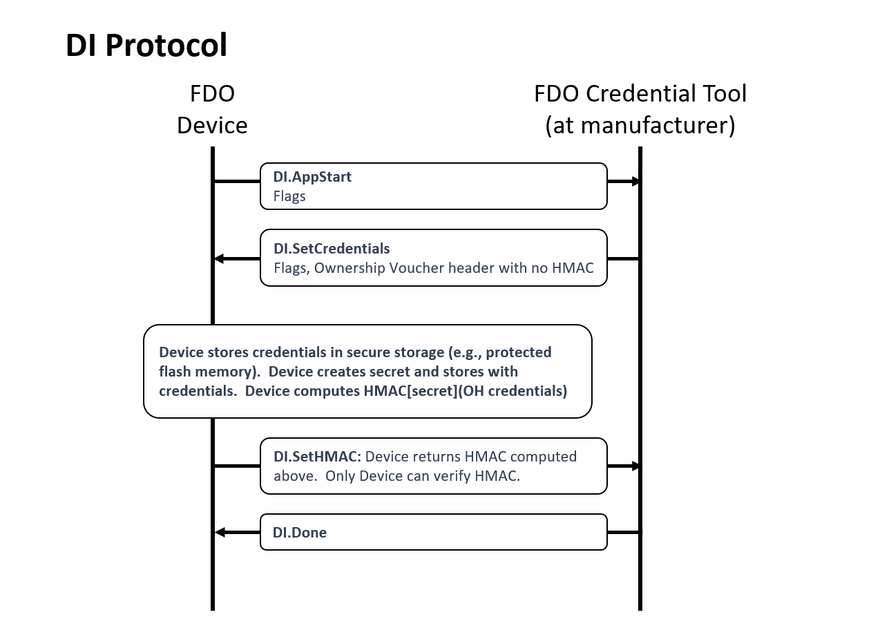
CDDL
DIProtocolMessages /= (
    DI.AppStart,
    DI.SetCredentials,
    DI.SetHMAC,
    DI.Done
)
5.2.1. DI.AppStart, Type 10
From Device ROE to Manufacturer:
The App Start message starts talking to the ROE application to start. Downloading, verifying, and starting the ROE application is outside the scope of this document.
Message Format:
DI.AppStart = [
    CapabilityFlags,
    VendorCapFlags,
    DeviceMfgInfo,
]
DeviceMfgInfo = bstr .cbor any
HTTP Context:
POST [URLPREFIX]/10
Message Meaning:
Start the process of taking initial ownership of the device.
Capability and vendor flags are processed as described in section § 3.3.2 CapabilityFlags & VendorCapFlags.
The device can include a serial number or other identifying mark
from the hardware (such as are available) in this message, using DeviceMfgInfo. This is intended to help
the manufacturing station to index FDO information with other information
available to the manufacturer. If no such information is available, DeviceMfgInfo
is sent with a CBOR null value.
The manufacturing station SHOULD be able to accept any legal value of
DeviceMfgInfo, even if the value cannot be interpreted.
5.2.2. DISetCredentials, Type 11
From Manufacturer to Device ROE:
Message Format:
DI.SetCredentials = [
    CapabilityFlags,
    VendorCapFlags,
    bstr .cbor OVHeader
]
HTTP Context:
-
POST response
-
includes authorization token
Message Meaning:
Capability and vendor flags are processed as described in section § 3.3.2 CapabilityFlags & VendorCapFlags.
The manufacturing station sends credentials to the Device ROE. The credentials
in OVHeader are identical to the OVHeader field of the Ownership Voucher.
Note that OVHeader is wrapped in a byte string, as it is in the
Ownership Voucher.
Some
additional credentials allow the original manufacturer of the device to be
determined across future ownership transfers.
The manufacturing
station computes the Hash of the device certificate chain (provided by the
manufacturer to the manufacturing tool) and includes the Hash as OVHeader.OVDevCertChainHash in the
message.
The manufacturing station typically will use the DeviceMfgInfo determine
information for OVHeader.OVRVInfo, OVHeader.OVDeviceInfo and OVHeader.OVPublicKey.
The OVHeader.OVGuid field (GUID) SHALL be a
secure randomly created unique identifier that is not derived from
device-specific information (this requirement is to ensure the privacy of the protocol). The Device
ROE allocates a secret, stores this information in the Device ROE within
the DeviceCredential, along with the secret. A hash of the public key OVHeader.OVPubKey is stored as a
DeviceCredential.DCPubKeyHash.
The Device ROE also computes an HMAC based on the above secret and the entire contents of this message body (including the brace brackets). This HMAC is used in the next message.
Potential uses for DeviceMfgInfo:
-
model number and/or serial number of the device, used as a database search key
-
certificate chain for device key to be used with FDO, where the device stores part of this chain in an earlier stage of manufacturing.
5.2.3. DI.SetHMAC, Type 12
From Device ROE to Manufacturer:
Message Format:
DI.SetHMAC = [
    Hmac
]
HTTP Context:
POST [URLPREFIX]/12
Message Meaning:
The device ROE returns the HMAC of the internal secret and the DI.SetCredentials.OVHeader tag, as mentioned above. The manufacturer combines this HMAC with its own transmitted information to create an Ownership Voucher with zero entries.
5.2.4. DIDone, Type 13
From Manufacturer to Device ROE:
Message Body:
DI.Done = [] ;; empty message
HTTP Context:
-
POST response with token
Message Meaning:
Indicates successful completion of the DI protocol. Before this message is sent, credentials associated with the device SHOULD be persisted in the manufacturing backend in a recoverable manner.
Upon receipt of this message, the device persists all information associated with the Device Initialization protocol.
5.2.5. Normative Requirements for FDO Initialization
FDO can be initialized in the Device using the DI protocol or any other means. After the FDO Device is initialized, the Device' stored configuration MUST include a device key and all the information in the DeviceCredential type, as described in section § 3.4.1 Device Credential Persisted Type (non-normative). In other words, each field of DeviceCredential must be stored suitably in the device.
The stored configuration (device key and DeviceCredential field data) MUST BE:
-
Suitably encoded so that it can be used by the Device to perform the TO1 and TO2 protocols
-
Persisted in the Device so that it can be accessed when the FDO protocol is needed to be run
-
Secured in the Device sufficiently so that attackers anticipated by the Device' security model are unable to extract it
The Device Certificate is not among this information, since it is not used by the device in the normative FDO protocols. However, it MAY be stored in the device. For example, it can be used as a client certificate when mTLS is the transport for the TO2 protocol.
The Device Key and the DeviceCredential.DCHmacSecret SHOULD be stored in the Device with Confidentiality, Availability and Integrity. All other DeviceCredential fields SHOULD be stored with in the Device with Availability and Integrity.
The levels of Confidentiality, Availability and Integrity needed depend on the security requirements of the hardware and software applications using FDO and/or relying on data transmitted using FDO.
5.3. Transfer Ownership Protocol 0 (TO0)
The function of Transfer Ownership Protocol 0 (TO0) is to register the new
owner’s current Internet location with the Rendezvous Server under the GUID of
the device being registered. This location is formatted into a 'blob'
of data, which includes an array of type RVTO2Addr with addressing
options for the Device. The Rendezvous Server negotiates a length of time
during which it will remember the rendezvous 'blob.' If the new
owner does not receive a device transfer of ownership within this time, it must
re-connect to the Rendezvous Server to repeat Transfer Ownership Protocol 0.
Transfer Ownership Protocol 0 MUST be implemented as a normative interface to each Rendezvous Server. This normative requirement ensures interoperability between Owners and Rendezvous Servers.
However, any given Owner and given Rendezvous Server MAY implement any interface or protocol to register the rendezvous information instead of using the TO0 protocol, so long as the state of the Rendezvous Server with respect to the Transfer Ownership Protocol 1 (TO1) is identical to that generated by the TO0 protocol specified here.
The protocol begins when the Owner Onboarding Service opens a connection to the Rendezvous Server. The Rendezvous Server is selected using RendezvousInfo from the Ownership Voucher. See § 3.8 RendezvousInfo.
The preferred protocol to use is TLS with server authentication only. The necessary client authentication is provided by the ownership voucher.

CDDL
TO0ProtocolMessages = (
    TO0.Hello,
    TO0.HelloAck,
    TO0.OwnerSign,
    TO0.AcceptOwner
)
5.3.1. TO0.Hello, Type 20
From Owner Onboarding Service to Rendezvous Server
Message Format:
TO0.Hello = [
    CapabilityFlags,
    VendorCapFlags
]
HTTP Context:
POST [URLPREFIX]/20
Message Meaning:
Initiates the TO0 Protocol, requests a Hello Ack nonce.
Capability and vendor flags are processed as described in section § 3.3.2 CapabilityFlags & VendorCapFlags.
5.3.2. TO0.HelloAck, Type 21
From Rendezvous Server to Owner Onboarding Service
Message Format:
CDDL
TO0.HelloAck = [
    CapabilityFlags,
    VendorCapFlags,
    NonceTO0Sign_Prep
]
HTTP Context:
-
POST response
-
includes authorization token
Message Meaning:
Requests proof of the Ownership Voucher.
Capability and vendor flags are processed as described in section § 3.3.2 CapabilityFlags & VendorCapFlags.
NonceTO0Sign_Prep sent to the Owner Onboarding Service; is later returned to the Device as TO0.OwnerSign.NonceTO0Sign.
5.3.3. TO0.OwnerSign, Type 22
From Owner Onboarding Service to Rendezvous Server
Message Format:
CDDL
CertChainOrNull     = X5CHAIN / null  ;; null when delegate unused

TO0.OwnerSign = [
    CapabilityFlags,    ;; Response capability flags.
    VendorCapFlags,
    bstr .cbor to0d,    ;; TO0 protocol parameters, not used in TO1
    to1d     ;; TO1 blob being provided from Owner
]
;; to0d is covered by the signature of to1d, using a hash
to0d = [
    OwnershipVoucher, ;; Ownership Voucher (complete)
    WaitSeconds,      ;; how many seconds to wait.
    NonceTO0Sign,     ;; Freshness of signature
]
WaitSeconds = uint32

;; to1d is the "rendezvous blob" that the Owner sends to the
;; Device via the rendezvous server.
;; To1d is used for both the to0 protocol and the to1 protocol
;; To1d is signed by the Owner key if DelegateChain is `Null`.
;; If DelegateChain is non-null, To1d must be signed by the Delegate Key
;;    referenced in the delegate chain.
to1d = CoseSignature
to1dBlobPayload = [
    to1dRV:       RVTO2Addr, ;; choices to access TO2 protocol
    to1dTo0dHash: Hash       ;; Hash of to0d from same to0 message
    DelegateChain .cbor CertChainOrNull ;; Optional - Delegate
]
$COSEPayloads /= (
    to1dBlobPayload
)
HTTP Context:
POST [URLPREFIX]/22
Message Meaning:
Responding CapabilityFlags and VendorCapFlags are presented.
The new owner demonstrates its credentials for a given GUID by providing the
Ownership Voucher and signing with the Owner Key. In addition, the owner
provides the network address(s) where it is waiting for a Device to connect
(entries in the RVTO2Addr array)
and upper bound of how long it is willing to
wait (to0d.WaitSeconds). The wait time is negotiated with the server, see
TO0.AcceptOwner.WaitSeconds. After the negotiated wait time passes, the owner must re-run
the TO0 Protocol to refresh its mapping.
The Ownership Voucher is given in to0d.OwnershipVoucher as a single object. The Ownership
Voucher must have at least one entry, i.e., len(to0d.OwnershipVoucher.OVEntries) > 0, or the
Rendezvous Server MUST fail the connection. The Rendezvous Server cannot verify an ownership voucher with zero
entries. The Rendezvous Server MAY
also restrict the maximum number of entries it is willing to accept, to prevent
DoS attacks. The current recommended maximum is ten entries. The
Rendezvous Server MAY also restrict the maximum blob size it is
willing to accept. It is recommended that Rendezvous Servers accept a
RVTO2Addr array of at least 3 entries.
If the Owner is a Delegate (see § 3.5 Delegation), the authorization is
via DelegateChain and the Owner key within the Delegate certificate
must match the Owner key in the last message of the ownership voucher.
This also requires the presented Delegate Chain to express the fdo-ekt-permit-redirect
permission. Any attempt to use a Delegate signature without this permission
MUST terminate with a DELEGATE_NOT_PERMITTED error.
The encoding of this message is divided into two objects: to0d and
to1d, which are linked by the hash to1dTo0dHash inside of to1d. The object to0d
contains fields that are only used in the TO0 Protocol, and the object to1d
contains fields that are also used in the TO1 Protocol.
The fields in to0d are:
to0d.OwnershipVoucher:
|
The entire Ownership Voucher. The Owner Key is given in the last
OwnershipVoucherEntry. The Owner key is used to verify the COSE
signature in |
to0d.WaitSeconds:
|
The wait time offered by the Owner, which is adjusted and confirmed in
|
to0d.NonceTO0Sign:
|
A copy of |
The to1d object is a signed "blob" that indicates a network
address (RVTO2Addr) where the
Device can find a prospective Owner for the TO2 Protocol. The entire object is stored by the
Rendezvous Server and returned verbatim to the Device in the TO1
Protocol. This value is verified by the Device at a later time (§ 5.5.7 TO2.ProveOVHdr20, Type 83).
The fields in to1d are as follows. RVTO2AddrEntry fields are
listed after an ellipsis, such as: to1d...RVIP instead of to1d.RVTO2Addr.RVTO2AddrEntry[i].RVIP
to1d...RVIP:
|
An internet address where the Owner is listening for a TO2
connection. It MAY be CBOR null if only |
to1d...RVDNS:
|
A DNS name where the Owner is listening for a TO2 connection.
Any IP address resolved by the DNS name must be equivalently able to process
the TO2 connection. A CBOR null MAY be used if only the |
to1d...RVPort:
|
A TCP- or UDP-port where the Owner is listening for a TO2 connection. A value of CBOR null indicates that the default port for the protocol (80 for HTTP or 443 for HTTPS) is used. |
to1d...RVProtocol:
|
The protocol to use to contact the Owner in the TO2 connection. The
CDDL type |
to1d.to1dTo0dHash:
|
A SHA256 or SHA384 hash of the TO0.OwnerSign.to0d CBOR object. The Rendezvous Server MUST verify that to0dh matches the hash of the to0d object. Otherwise, the Rendezvous Server SHALL end the connection in error. SHA384 is used if the selected Device cryptography includes SHA384. The bstr wrapping |
A given Rendezvous Server MAY choose to reject Ownership Vouchers that are not trusted.
If the Rendezvous Server has no basis on which to trust the Ownership Voucher,
it must apply its own internal policies to protect itself against a DoS attack,
but can otherwise safely provide the Rendezvous Server (i.e., it can allow the
TO0 and TO1 Protocols to succeed). This behavior is acceptable because the TO2
Protocol is able to verify the to1d “blob” defined in this message. However,
such a Rendezvous Server must ensure that untrusted Ownership Vouchers cannot
degrade the service for trusted Ownership Vouchers. This can be accomplished
through hard limiting of resources, or even allocating a trusted- and
non-trusted version of the service.
The Rendezvous Server needs to verify that the signature on this message is verified by the public key on the last message of the ownership voucher, such as by saving the public key transmitted and verifying it is the same public key.
When the device certificate is non-null, the Rendezvous Server must verify the binding of the certificate to the Ownership Voucher (verify the certificate chain hash). It is the only non-owner entity which can do this. It is recommended that the Server also do revocation check for the certificate chain.
A Rendezvous Server in a trusted context (e.g., a closed network), MAY simplify implementation by not performing the above verifications and allowing the TO2 protocol to perform all verification.
5.3.4. TO0.AcceptOwner, Type 23
From Rendezvous Server to Owner Onboarding Service
HTTP Context:
Message Format:
TO0.AcceptOwner = [
    WaitSeconds
]
HTTP Context
-
POST response with token
Message Meaning:
Indicates acceptance of the new Owner’s information.
The Rendezvous Server will associate GUID
with the new owner’s address information for WaitSeconds seconds.
WaitSeconds MAY NOT exceed TO0.OwnerSign.waitSeconds, but it MAY be less.
If the GUID indicated in:
TO0.OwnerSign.to0d.OVHeader.OVGuid
is already associated with another IP address, and Delegation is not in use, the Rendezvous Server re-targets this association as specified in this protocol.
The Owner Onboarding Service can drop the connection after this message is processed.
If the new Owner does not receive a Transfer Ownership connection from a Device
within WaitSeconds seconds, it must repeat Transfer Ownership Protocol 0 and
re-register its GUID to address association.
When the new Owner is actively changing its address from time to time (e.g., to mask its identity), the frequency of changing address dictates the magnitude of WaitSeconds. Otherwise, the negotiation depends on the frequency at which the new owner wishes to refresh the server, traded off with the server’s need to remember many GUID associations.
The Rendezvous Server has no sure way to know when a device ownership is successful or fails, since it is not party to the TO2 Protocol. This is intended to make it harder for an intruder who is monitoring the Rendezvous Server to trace a device, even by the FDO GUID (which is replaced in the TO2 Protocol). Thus the Rendezvous Server MAY arrange to keep the timeouts short enough that it does not have to keep every FDO transaction ever created in its database. We imagine a timeout of a day or two, or perhaps a week or two.
When Delegation is in use, a Rendezvous server MAY cache Rendezvous blob’s for a single non-Delegate Owner and multiple Delegates.
When a Delegate registers using this message,
TO0.OwnerSign...DelegateChain is non-Null. In this case the new
blob is added to zero or more Rendezvous entries associated with the
Delegate. An entry from the same Delegate is replaced with the new
entry, but entries from other Delegates or from the (non-Delegate)
Owner are not modified. Individual Rendezvous entries, whether from
Delegate or Owner, are independently timed out at the Rendezvous server.
5.4. Transfer Ownership Protocol 1
Transfer Ownership Protocol 1 (TO1) finishes the rendezvous started between the New Owner and the Rendezvous Server in the Transfer Ownership Protocol 0 (TO0). In this protocol, the Device ROE communicates with the Rendezvous Server and obtains the IP addressing info for the prospective new Owner. Then the Device can establish trust with the new Owner by connecting to it, using the TO2 Protocol.
-
The Transfer Ownership Protocols 0 and 1 serve only to get the Device the IP addressing information for a potential Owner candidate—no trust is conveyed in these protocols.
When possible, the TO1 Protocol to the Rendezvous Server is encapsulated under HTTPS, to protect the privacy of the Owner. It is possible that intermediate stages of the end-to-end protocol connection are run under HTTP, such as from a constrained device to a gateway or from a ROE to an OS user process.
If it is NOT possible to use HTTPS to protect the TO1 Protocol, the Owner MAY also take measures to protect its privacy:
-
The Owner MAY use a private IP address (e.g., IPv6 privacy address) and refresh the address periodically, to make it more difficult for an attacker to glean information from the rendezvous address(es) in RVTO2Addr.
-
The Owner MAY use a multi-tenant model, where the actual Owner of the Device does not relate to the IP address or DNS name of the Owner.
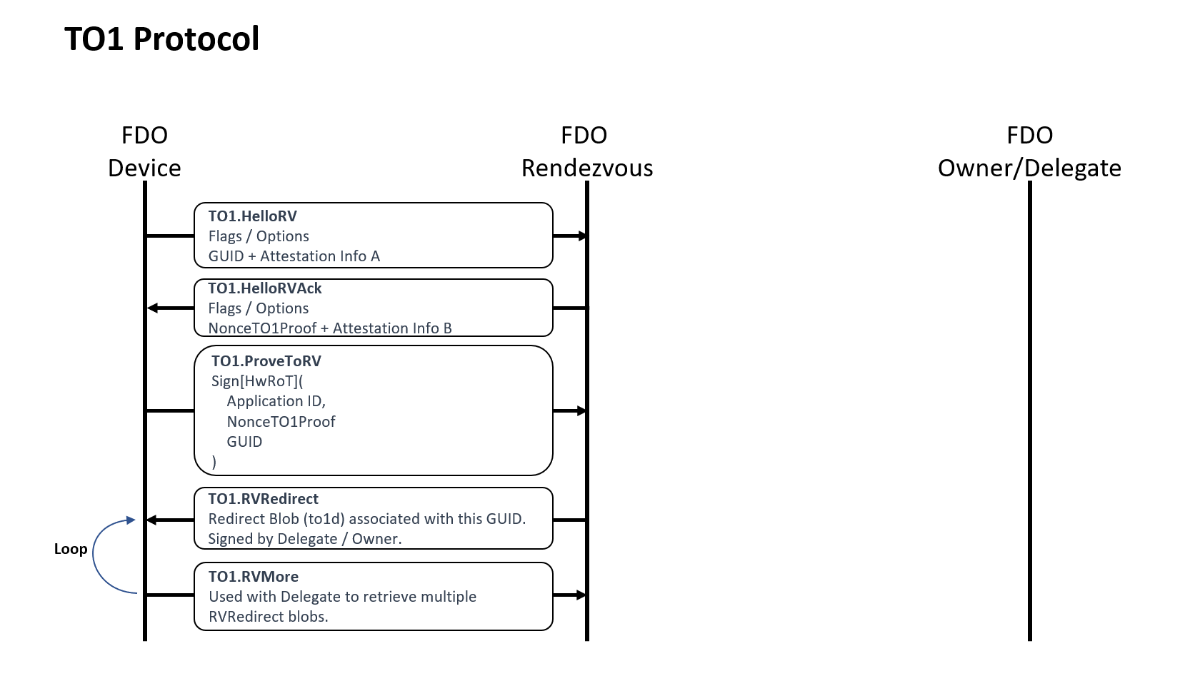
CDDL
TO1ProtocolMessages = (
    TO1.HelloRV,
    TO1.HelloRVAck,
    TO1.ProveToRV,
    TO1.RVRedirect
    TO1.RVMore
)
5.4.1. TO1.HelloRV, Type 30
From Device ROE to Rendezvous Server:
Message Format:
TO1.HelloRV = [
    CapabilityFlags,
    VendorCapFlags,
    Guid
]
HTTP Context:
POST [URLPREFIX]/30
Message Meaning:
Establishes the presence of the device at the Rendezvous Server.
The "CapabilityFlags" and "VendorCapFlags" are processed before the rest of the message. See § 3.3.3 CapabilityFlags.
The “Guid” parameter is the GUID of the Device. This is used as an index by the Rendezvous Server to look up information associated with the Device.
If the Rendezvous Server does include a record for this Guid, processing in this protocol continues.
If the Rendezvous Server does not include a record for this Guid, then it returns an ERROR message and terminates the TO1 protocol (see error RESOURCE_NOT_FOUND; § 5.1.1.1 Error Code Values). The Device will continue to try to onboard, perhaps using a different Rendezvous Server or perhaps finding the Guid on this one at a later time, following the mandated interpretation of RendezvousInfo.
However, a Rendezvous Server which does not include a record for this Guid, but knows of a second Rendezvous Server that does include such a record MAY respond with one of the following HTTP messages:
302 Redirect (HTTP 1.0)
307 Temporary Redirect (HTTP 1.1 and later)
In this case, the FDO device SHOULD immediately attempt a Transfer Ownership 1 (TO1) Protocol connection to the redirect URL in the return message.
The following issues are outside the scope of this document:
-
How the Rendezvous Server knows that a second Rendezvous server includes a record for the Guid
-
How the Rendezvous Servers cooperate to prevent permanently looping redirects
However, a Rendezvous Server MAY NOT respond with a HTTP 302 or 307 message unless it has solved these issues.
It is possible that the second Rendezvous server, referenced in a HTTP 302 or 307 message, is inaccessible to the Device. In this case, the Device will timeout and fail to access the second Rendezvous server. As for any device timeout, the Device MUST continue to attempt new FDO connections.
5.4.2. TO1.HelloRVAck, Type 31
From Rendezvous Server to Device ROE
Message Format:
TO1.HelloRVAck = [
    CapabilityFlags,
    VendorCapFlags,
    NonceTO1Proof_Prep
]
HTTP Context:
-
POST response, includes authorization token
Message Meaning:
Sets up Device ROE for next message.
The "CapabilityFlags" and "VendorCapFlags" are processed before the rest of the message. See § 3.3.3 CapabilityFlags.
The NonceTO1Proof_Prep tag contains a nonce to use as a guarantee of
signature freshness as NonceTO1Proof in TO1.ProveTORV.
5.4.3. TO1.ProveToRV, Type 32
From Device ROE to Rendezvous Server:
Message Format:
TO1.ProveToRV = EAToken
$$EATPayloadBase //= (
    EAT-NONCE: NonceTO1Proof
)
HTTP Context:
POST [URLPREFIX]/32
Message Meaning:
Proves validity of device identity to the Rendezvous Server for the Device seeking its owner, and indicates its GUID.
MAROEPrefix MAY be used to provide evidence of the ROE application that is running.
NonceTO1Proof proves that the signature was just computed, and not a reply (signature ‘freshness’ test). EAT-UEID contains the FDO Guid, as described in § 3.3.8 EAT Signatures.
The signature is verified using the device certificate chain contained in the Ownership Voucher.
If the device signature cannot be verified, or fails to verify, the connection is terminated with an error message (§ 5.1.1 Error - Type 255).
5.4.4. TO1.RVRedirect, Type 33
From Rendezvous Server to Device ROE:
Message Format:
TO1.RVRedirect = [
    numTo1ds: uint,
    idxTo1ds: uint,
    msgTo1ds: [ to1d ]
]
HTTP Context:
-
POST response, with token
Message Meaning:
Indicates to the Device ROE that a new Owner, and perhaps one or more Delegates, are indeed waiting for it
-
numTo1dsis the number ofto1dobjects being transmitted from the Rendezvous server, which might be more than fit into a single message. -
idxTo1dsis the index of the firstto1din this message’smsgTo1dsarray.idxTo1ds = 0for the first message sent. -
msgTo1dsentries contain Rendezvous blobs. The RVTO2Addr fields in these blobs indicate potential Owner or Delegate addresses. -
See definition of
RVTO2Addr(§ 3.3.16 RVTO2Addr (Addresses in Rendezvous 'blob')) and additional instructions for interpreting theRVTO2Addr(§ 4.3 Transmission of Messages over the HTTP-like Protocols). -
When Delegation is not in effect, there is exactly one
to1dobject. -
When Delegation is in effect, there can be zero or one non-Delegate entries and zero or more Delegate entries.
When the last to1d blob is received, the TO1 protocol is complete.
For a (non-Delegate) Owner, there is exactly one TO1.RVRedirect
message. numTo1ds is always one (1) and idxTo1ds is always zero (0).
For a Delegate, the TO1.RVRedirect message contains as many to1d
blobs as will fit. numTo1ds indicates the total number of
blobs being returned over all RVRedirect messages, and idxTo1ds
gives the zero-based index of the first to1d object in msgTo1ds.
When all to1d objects have been received, the TO1 protocol is
complete.
If more than one TO1.RVRedirect message is needed (this is only
possible in the Delegate case), the Device requests additional
TO1.RVRedirect messages using the TO1.RVMore message.
5.4.5. TO1.RVMore
From Device ROE to Rendezvous Server:
Message Format:
TO1.RVMore = [
    idxTo1ds: uint
]
HTTP Context:
POST [URLPREFIX]/32
Message Meaning:
This message is only invoked when Delegation is in use and the
number of to1d blobs stored in the Rendezvous server exceeds the
FDO message size. When Delegation is not in use, only a
single to1d object is transmitted, and this message is not used.
The message sequence that does use this message is thus:
-
TO1.ProveToRV
-
TO1.RVRedirect (transmits some blobs)
-
TO1.RVMore
-
TO1.RVRedirect (transmits more blobs)
-
TO1.RVMore (as needed, until all blobs are transmitted)
-
...etc...
Each RVRedirect SHOULD be filled with as many to1d objects as
possible, to keep the number of iterations down.
The idxTo1ds parameter gives the (zero-based) index of the next
to1d object to be received. The order of the to1d responses (and
the index of each to1d) is not guaranteed from the Rendezvous
server, although it SHOULD be stable over short periods of time, to
make this message sequence work properly.
If the transmitted redirects are not received, the RVMore is retransmitted by the Device, as per normal FDO connection maintenance.
The Device MUST cache to1d results
before trying any of them using the TO2 protocol, so that the TO1 and
TO2 protocols do not overlap. If the Device cannot cache all results,
it MAY discard later to1d results. Then, if the Device
needs additional potential Delegates, it SHOULD cache the
results tried, or their number, and re-try the TO1 protocol, skipping
blobs it believes have already been tried.
Similarly, enterprises using Delegation SHOULD configure FDO so that
the number of to1d objects returned at once is small.
A FDO implementation that does not support Delegation does not need to support the RVMore message loop.
5.5. Transfer Ownership Protocol 2
After the TO1 protocol is complete, the Device uses the Rendezvous 'blob' information to initiate communications with the Owner Onboarding Service in the TO2 protocol.
The TO2 Protocol is the most complicated of the protocols in FDO, because it has several steps that are not present in other protocols:
-
Establishes trust in both directions: The Device uses its device attestation key and the Owner uses the Ownership Voucher.
-
Creates an encrypted channel, based on the above trust, using a supported key exchange mechanism.
-
Exchanges device service info for owner service info.
-
The Owner replaces all FDO credentials in the Device (this does not include the Device’s attestation key and certificate); the Device gives the Owner an HMAC that allows it to generate a replacement Ownership Voucher. The Owner can use this new Ownership Voucher in future FDO transactions (e.g., to resell the Device).
In addition, in all these operations, all unbounded data items are divided across multiple messages, to limit the size of an individual message that the Device is required to process. This causes several loops in the protocol:
-
The Ownership Voucher is transmitted header first, then entry by entry in successive messages.
-
The service info (in each direction) is transmitted in as many messages as necessary to keep the message size to a single packet. A constrained device MAY assume that the connection MTU size is 1500 bytes. The Owner and Device can simplify the implementation by limiting the size of each ServiceInfo message 1300 bytes, to allow room for protocol headers.
-
The Owner and Device MAY change the maximum ServiceInfo message the other entity is able to send, using the fields:
TO2.DeviceServiceInfoRdy20.maxOwnerServiceInfoSz
and
TO2.OwnerServiceInfoReady.maxDeviceServiceInfoSz
Implementation note: A larger or smaller maximum ServiceInfo size provides a tradeoff between buffering requirements and the ability to transmit bulk data with fewer roundtrip times. As an additional tradeoff, an implementation can choose to parse CBOR bulk data incrementally to allow larger messages to be sent without needing a full message buffer.
The ServiceInfo exchange in FDO allows the cooperating client entities on the Device and Owner to negotiate their own “protocol” for setting up the Device. The names and meanings of key value pairs is generally up to the Device and Owner, but examples are given above. See § 3.9 ServiceInfo and Management Service – Agent Interactions.
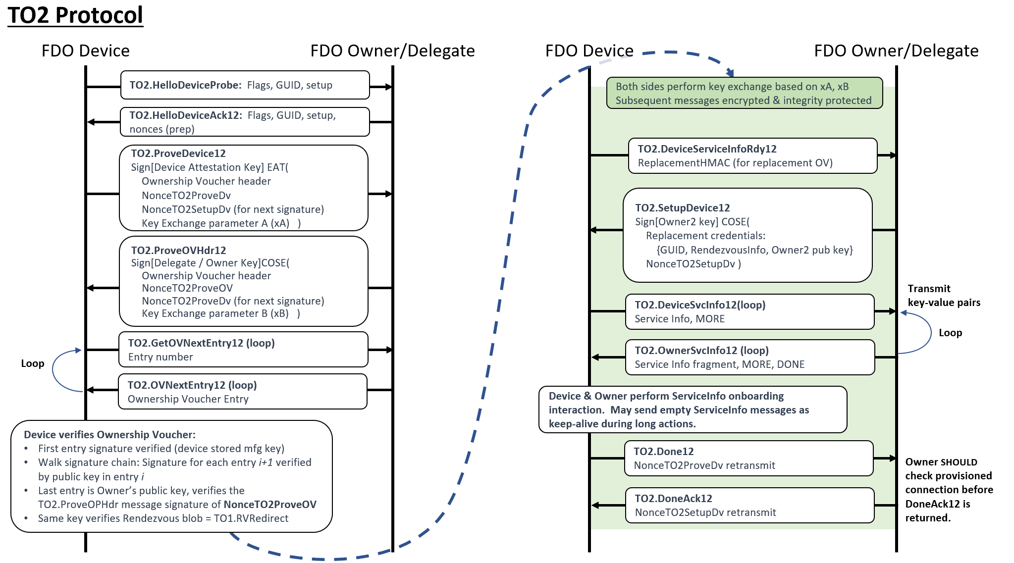
5.5.1. TO2 Protocol version 2.0
In FDO version 2.0, almost all messages are labeled with ``20.'' This makes it easier for implementations to use the message names as procedure names when multiple versions of FDO are supported.
The sequencing of the messages is similar to previous versions of FDO. Some changes:
-
CapabilityFlags and VendorCap flags have been integrated into the initial handshake. The initial message is called a "probe" because we intend it to be similar in all future versions of FDO.
-
The verification of the Owner (using the Ownership Voucher) happens before the verification of the Device. This is intended to mitigate a potential DoS attack on less powerful Devices. The SetupDevice message is merged with the Owner ServiceInfo Ready message to make the protocol "ping-pong of messages" work out without adding a round-trip time.
-
The only change to the cryptography is the removal of EPID. This also simplifies the signing sub-protocol, since 2 of the 3 steps were only used by EPID.
-
We anticipate an update to add quantum computer resistant (aka PQ-safe) cryptography soon, perhaps without a full FDO release. Some authorities have recommended increasing the power of the conventional cryptosystems in the short term; the more powerful conventional crypto is available in all versions of FDO, so this accommodation is left up to the implementor.
5.5.2. Limitation of Round Trips
The implementation shall complete the Transfer Ownership Protocol 2 in no more than 1,000,000 round trips, overall. Owner and Device implementations SHOULD NOT request more iterations than this.
A given Owner implementation MAY limit the number of ServiceInfo iterations received from a Device, to prevent a denial of service attack.
5.5.3. TO2 Protocol Messages
CDDL
TO2ProtocolMessages = (
    TO2.HelloDeviceProbe,
    TO2.HelloDeviceAck20,
    TO2.ProveDevice20,
    TO2.ProveOVHdr20,
    TO2.GetOVNextEntry20,
    TO2.OVNextEntry20,
    TO2.DeviceServiceInfoRdy20,
    TO2.SetupDevice20,
    TO2.DeviceSvcInfo20,
    TO2.OwnerSvcInfo20,
    TO2.Done20,
    TO2.DoneAck20
)
5.5.4. TO2.HelloDeviceProbe, Type 80
From Device ROE to Owner Onboarding Service
Message Format:
TO2.HelloDeviceProbe = [
    CapabilityFlags,
    VendorCapFlags,
    Guid,
    maxDeviceMessageSize,
    hashTypes: [ hashtype+ ],
    sugar
    # add: Options
]
maxDeviceMessageSize = uint16
sugar = octet[16]
HTTP Context:
POST [URLPREFIX]/80
Message Meaning:
This message is the initial message for a TO2 connection. It probes the server for support of FDO. It is also used to probe the connection for supported versions. In addition, it also identifies the GUID to allow the server to determine if it can support this connection (i.e., if it has ownership credentials sufficient to support onboarding).
Capability and vendor flags are processed as described in section § 3.3.2 CapabilityFlags & VendorCapFlags.
The maxDeviceMessageSize indicates the maximum sized FDO
message the Device is able to receive, buffer, and decode. A value of
zero indicates the default message size. The Owner MAY use this value
to adjust the size of messages sent to the device, but only starting
with TO2.OVNextEntry. The default message size applies to
TO2.ProveOVHdr20.
The Guid indicates the Guid within the Device Credentials and the
Ownership Voucher.
The hashTypes array indicates at least one hash type (see § 3.3.4 Hash / HMAC)
supported by this Device. The Owner will choose one of these types to
generate the TO2.HelloDeviceAck20.hashPrev field.
The Owner chooses one of the hash types specified, and computes a Hash object of these fields concatenated together.
-
TO2.HelloDeviceProbe(the contents of this message) -
Hash[
OVHeader.OVPublicKey] (=DeviceCredential.DCPubKeyHash)
The hash of OVHeader.OVPublicKey is a Hash object (see
§ 3.3.4 Hash / HMAC), to match DeviceCredential.DCPubKeyHash. This can be
computed dynamically or cached on the Owner.
This hash object is used in TO2.ProveDevice20, below.
The sugar field in
this message is intended to add entropy to this hash. The sugar
value MUST be regenerated when this message is targeted to a new
destination IP address. Retransmissions of this message SHOULD use
the same value of sugar to increase protocol robustness.
5.5.4.1. Using TO2.HelloDeviceProbe to Probe FDO Version Support
The TO2.HelloDeviceProbe message is intended to allow a FDO client to indicate supported FDO versions to the FDO Owner, as follows:
-
FDO Device sends TO2.HelloDeviceProbe message to FDO server, including CapabilityFlags for all supported versions. If the FDO device supports versions 1.0 or 1.1, it can still use this message (in FDO 2.0), even if the CapabilityFlags indicate that it does NOT support version 2.0, beyond this message.
The envelope for this message is always for FDO 2.0. This does NOT indicate that the FDO Device supports version 2.0, only that it supports version negotiation.
-
FDO Owner examines versions the FDO Device supports, chooses the best version to use with this and responds with a message indicating the FDO version it has selected. The envelope of this message indicates the selected version (i.e., for HTTP the URL indicates the selected version).
-
The FDO Device responds using the FDO Server’s selected version.
5.5.5. TO2.HelloDeviceAck20, Type 81
;; This message acknowledges the initial message.
TO2.HelloDeviceAck20 = [
    CapabilityFlags,
    VendorCapFlags,
    Guid,
    maxOwnerMessageSize,
    kex: keyExchangeSuites, # key exchange suites
    ciphers: cipherSuiteArray,
    NonceTO2ProveDV_Prep, ;; used later
    Hash hashPrev  ;; hash[TO2.HelloDeviceProbe] -- to verify that
                   ;; previous message was not modified
]
maxOwnerMessageSize = uint16
cipherSuiteArray = [ CipherSuites+ ]
keyExchangeSuites = [ KexSuiteNames+ ]
HTTP Context:
POST [URLPREFIX]/101
Message Meaning:
This message acknowledges the TO2.HelloDeviceProbe message. The
message prepares the device to perform attestation in the next
message.
Capability and vendor flags are processed as described in section § 3.3.2 CapabilityFlags & VendorCapFlags.
The maxOwnerMessageSize indicates the maximum sized FDO message the Owner is
able to receive, buffer, and decode. The Device MAY use this value to
adjust the size of messages sent to the Owner. A value of zero
indicates the default message size.
The kex and ciphers fields indicate the key
exchange protocols and cipher suites the device is able to support.
At least one entry is required.
A constrained device MAY select only a single choice. A non-constrained device
might have several suites to choose from.
The FDO server SHOULD support as many cipher suites as possible.
The values for kexSuiteName (KexSuiteNames) are given in: § 3.7 Key Exchange in the TO2 Protocol
The cipher suite cipherSuiteName (CipherSuites) is as given in: § 4.4 Encrypted Message Body
The NonceTO2ProveDV_Prep value is provided to test the freshness of the
signature in the TO2.ProveDevice20 message.
The hashPrev value is a hash of the
TO2.HelloDeviceProbe message received. It is used in the
TO2.ProveDevice20 message to verify the two unsigned messages,
TO2.HelloDeviceProbe and TO2.HelloDeviceAck20.
The receiver MUST compute and save a hash of the previously
transmitted TO2.HelloDeviceProbe message, and
verify that hashPrev matches this hash. (The hash is
with a value that is known from the device initialization, if possible).
5.5.6. TO2.ProveDevice20, Type 82
From Device ROE to Owner Onboarding Service:
Message Format:
TO2.ProveDevice20 = EAToken
$$EATPayloadBase //= (
    EAT-NONCE: NonceTO2ProveDv  ;; must equal the one that was just sent.
)
TO2ProveDevicePayload20 = [
    kexSuiteName,    ;; eg: 'ECDH384'
    cipherSuiteName, ;; eg: 3 (AES256GCM)
    xAKeyExchange,
    NonceTO2ProveOV_Prep ;; NonceTO2ProveOV is used in TO2.ProveOVHdr20 and TO2.DoneAck20
    hashPrev2 ;; = hash[TO2.HelloDeviceAck20]
]
$EATPayloads /= (
    TO2ProveDevicePayload20
)
kexSuiteName = tstr
cipherSuiteName = CipherSuites
Message Meaning:*
This message contains the attestation of the FDO Device to the FDO Owner. The attestation proves the authenticity of the device with respect to the Device certificate in the Ownership Voucher.
This message also verifies and acknowledges the protocol’s initial two
messages. The "hashPrev2" field contains a hash of the previous
message (TO2.HelloDeviceAck20), which in turn contains a hash of
its previous message (TO2.HelloDeviceProbe). The Owner MUST
compute the hash of the messages that it has received. If hashPrev or
hashPrev2 differ from the hashes it computes, the Owner MUST drop the
connection, and SHOULD send an error message.
If an attacker modifies hashPrev or hashPrev2 (e.g., to match the
modifications that the attacker has done to the messages), the
signature of this TO2.ProveDevice20 message will fail, so the Owner
will reject the connection.
The kexSuiteName and cipherSuiteName fields select one offered
entry from each of the kexSuiteNames and cipherSuiteNames arrays
presented in the TO2.HelloDeviceProbe message. The decision of which
suites to choose, if there is a choice, is up to the FDO
Owner implementation. If the FDO Owner does not support at least one
key exchange (KEX) suite and one cipher suite from the list sent by
the FDO device, the connection is rejected and an Error message SHOULD
be transmitted.
It is recommended that the Device choose the strongest cipher suite supported, with a preference for PQ Safe (Post-Quantum safe) algorithms (when these are supported by FDO). Individual products MAY also take into account performance issues (e.g., hardware support) and expected product lifetime to make this decision. The Owner can also influence this decision, based on which crypto options are offered, in order to provide guidance of a change in the security of specific cryptography.
The xAKeyExchange field begins the key exchange protocol (in Diffie
Hellman, the parameter 'A'). See § 3.7 Key Exchange in the TO2 Protocol for more details on key
exchange. The key exchange is finished in the TO2.ProveOVHdr20
message.
5.5.7. TO2.ProveOVHdr20, Type 83
From Owner Onboarding Service to Device ROE:
Message Format:
TO2.ProveOVHdr20 = CoseSignature
TO2ProveOVHdrPayload = [
    bstr .cbor OVHeader,     ;; Ownership Voucher header
    NumOVEntries,            ;; number of ownership voucher entries
    HMac,                    ;; Ownership Voucher "hmac" of hdr
    NonceTO2ProveOV,         ;; nonce from TO2.HelloDevice
    xBKeyExchange,           ;; Key exchange, final step
    maxOwnerMessageSize
    OwnerPubKey: PublicKey   ;; Owner key, as convenience to Device
    DelegateChain: CertChainOrNull ;; Delegate certificate, where present
]
NumOVEntries = uint8
TO2ProveOVHdrUnprotectedHeaders = ()
$COSEPayloads /= (
    TO2ProveOVHdrPayload
)
$$COSEUnprotectedHeaders /= (
    TO2ProveOVHdrUnprotectedHeaders
)

maxOwnerMessageSize = uint16
HTTP Context:
-
POST response, includes authorization token
Message Meaning:
This message serves several purposes:
-
The Owner begins sending the Ownership Voucher to the device (only the header is in this message).
-
The Owner signs the message with the final Owner key in the Ownership Voucher, allowing the Device to verify (later on) that the Owner controls this private key. A delegate key, with a delegate certificate to authorize it, replaces the Owner key for a Delegate owner (see § 1.3.1 Delegation and Delegated Owners). In such a case, one of the
fdo-ekt-permit-onboard-permissions MUST be specified, or endpoint MUST terminate TO2 with aDELEGATE_NOT_PERMITTEDerror. -
The Owner completes the key exchange protocol by sending the key exchange parameter xBKeyExchange (e.g., in Diffie Hellman, the parameter ‘B’) to the Device.
The Ownership Voucher’s header is sent in the OVHeader and HMac
fields. The NumOVEntries value
gives the number of Ownership Voucher Entries. The Ownership Voucher entries will be sent in
subsequent messages. It is legal for this tag to have a value of zero (0),
but this is only useful in re-manufacturing situations, since the Rendezvous
Server cannot verify (or accept) Ownership Vouchers with no (0) entries.
NumOVEntries MUST be less than 256. If NumOVEntries is detected as larger than 255, all entities MUST reject the entry, aborting a protocol connection if necessary.
The HMac field is a HMAC-SHA256 or
HMAC-SHA384 over the OVHeader tag. The HMAC derives
from the Device initialization in DI.SetHMAC, or equivalent, and is based on a secret
allocated and stored in the Device.
The Device re-computes
the HMAC value against the received contents of the OVHeader tag using this stored
secret, and verifies that the HMac field has the same value. If the
values are different, the protocol ends in error.
This increases confidence that
the Device itself has not been reinitialized since it was originally programmed
during manufacturing.
The Owner Onboarding Service includes the hash of
device certificate chain from the Ownership Voucher (OwnershipVoucher.OVHeader.OVDevCertChain) in the
TO2.ProveOVHdr20 message (as OVDevCertChainHash) for the device to verify
with the HMAC. The device temporarily saves the cert chain hash on receiving the message. When
the device computes the new HMAC based on the fields received in TO2.SetupDevice
message, it uses the value of the cert chain hash that was previously
saved. The new HMAC is returned to the Owner Onboarding Service as part of TO2.Done20
message.
The public key (OwnerPubKey) is an early copy of
the Owner Key. This key, which verifies this message’s
signature, must be compared with the public key in the last Ownership
Voucher Entry when that is received later in the sequence of this
protocol. The presence of the Owner key in this message is a
convenience for the Device, giving it the option to verify the
signature of this message immediately, then compare the given
OwnerPubKey with the later transmission (when and if Delegate Protocol is
not being used).
Note: OVHeader.OVPubKey is the initial owner public key from the Ownership
Voucher Header, such as the key used in the factory when FDO was
initialized. The OwnerPubKey in this message is the key that
represents the Owner onboarding the Device, at the other end of the
supply chain.
The xBKeyExchange field completes the key exchange protocol. See § 3.7 Key Exchange in the TO2 Protocol for more details on key exchange.
The maxOwnerMessageSize indicates the maximum sized FDO message the Owner is
able to receive, buffer, and decode. The Device MAY use this value to
adjust the size of messages sent to the Owner. A value of zero
indicates the default message size.
OwnerPubKey MUST also be able to verify the signature of the TO1.RVRedirect
message. The Device must store the TO1.RVRedirect message (or its hash) until
the TO2.ProveOVHdr20 message is received. At this time, the Device can verify the
TO1.RVRedirect signature with the give Owner key in TO2.ProveOVHdr20.OVPubKey. If the
TO1.RVRedirect signature does not verify, the Device MUST assume that a man in
the middle is monitoring its traffic, and fail TO2 immediately with an error
message. (For more on validation, see § 5.6 Final Voucher Validation below)
The verification of this message is critical, if complex.
The Device initially verifies this message’s COSE signature using
the supplied OwnerPubKey, then saves a copy of this key (for memory reasons, the
Device MAY save a suitable hash of the key). A failure in verification
causes TO2 to terminate in error.
See § 5.6 Final Voucher Validation below for details on this process.
5.5.8. TO2.GetOVNextEntry20, Type 84
From Device ROE to Owner Onboarding Service:
Message Format:
TO2.GetOVNextEntry20 = [
    OVEntryNum
]
OVEntryNum = uint8
HTTP Context:
POST [URLPREFIX]/62
Message Meaning:
Acknowledges the previous message and requests the next Ownership Voucher Entry. The integer argument, OVEntryNum, is the number of the entry, where the first entry is zero (0).
The Device MUST send successive OVEntryNum values in subsequent TO2.GetOVNextEntry20.
5.5.9. TO2.OVNextEntry20, Type 85
From Owner Onboarding Service to Device ROE
Message Format:
TO2.OVNextEntry20 = [
    OVEntryNum
    OVEntry
]
HTTP Context:
-
POST response with token
Message Meaning:
Transmits the requested Ownership Voucher entry from the Owner Onboarding Service to the Device
ROE. The value of OVEntryNum matches the value of TO2.GetOVNextEntry20.OVEntryNum.
If OVEntryNum == TO2.ProveOVHdr20.NumOVEntries-1, then the next state is TO2.ProveDevice. Otherwise the next state is TO2.GetOVNextEntry.
The Device ROE verifies the ownership voucher entries incrementally as follows:
Variables from OVEntryPayload:
-
HashPrevEntry– hash of previous entry. The hash of the previous entry’sOVEntryPayload. For the first entry, the hash isSHA[TO2.ProveOVHdr20.OVHeader||TO2.ProveOVHdr20.HMac]. The bstr wrapping for the OVHeader is not included. -
PubKey– public key signed in previous entry (initialize withTO2.ProveOVHdr20.OVHeader.OVPubKey) -
HashHdrInfo– hash of GUID and DeviceInfo, compute from TO2.ProveOVHdr20 as:SHA[TO2.ProveOVHdr20.OVHeader.Guid||TO2.ProveOVHdr20.OVHeader.DeviceInfo]-
Pad the hash text on the right with zeros to match the hash length.
-
-
For each entry:
-
Verify signature TO2.OVNextEntry20.OVEntry using variable
PubKey -
Verify variable
HashHdrInfomatchesTO2.OVEntry20.OVEHashHdrInfo -
Verify
HashPrevEntrymatchesSHA[TO2.OVNextEntry20.OVEntry.OVEPubKey] -
Update variable
PubKeytoTO2.OVNextEntry20.OVEPubKey.OVPubKey -
Update variable
HashPrevEntrytoSHA[TO2.OVNextEntryPayload] -
If
OVEntryNum == TO2.ProveOVHdr20.NumOVEntries-1then verifyTO2.ProveOVHdr20.OwnerPubKey == TO2.OVNextEntry20.OVEntry.OVEPubKey
If any verification fails, the TO2 protocol ends in error.
Note: Subsequent message bodies are protected for confidentiality and integrity.
5.5.10. TO2.DeviceServiceInfoRdy20, Type 86
From Device ROE to Owner Onboarding Service
Message Format - after decryption and verification:
TO2.DeviceServiceInfoRdy20 = [
    ReplacementHMac, ;; Replacement for DI.SetHMAC.HMac or equivalent
    maxOwnerServiceInfoSz    ;; maximum size service info that Device can receive
    NonceTO2SetupDV_Prep, ;; nonce is used below in TO2.ProveDevice and TO2.DoneAck20
]
A null HMAC indicates acceptance of credential reuse protocol
ReplacementHMac = HMac / null
maxOwnerServiceInfoSz = uint16 / null
HTTP Context
POST [URLPREFIX]/66
Message Meaning:
This message signals a state change between the authentication phase of the protocol and the provisioning phase (ServiceInfo) negotiation.
The ReplacementHMac variable completes the information needed in the Owner Onboarding Service to create a new Ownership Voucher for the Device.
The field maxOwnerServiceInfoSz, if non-null, indicates the maximum size Owner ServiceInfo message that the Device is able to process from the Owner. This might indicate a decrease or increase in size from the recommended ServiceInfo limit of 1300 bytes per message. It is up to the Device to ensure that it can receive this message via the underlying transport mechanism. A null value of maxOwnerServiceInfoSz indicates the recommended maximum ServiceInfo size, as above.
If the Device supports the Credential Reuse protocol and all the conditions for Credential Reuse are satisfied in TO2.SetupDevice20, then it can return ReplacementHMac as CBOR null. See § 7 Credential Reuse Protocol for additional information on Credential Reuse protocol.
If ReplacementHMac is an HMac (i.e., non-null) ReplacementHMac MAY be used by the Owner to create a replacement Ownership Voucher for the device. This permits FDO to onboard the device again at a future date, without reinitializing the device outside of FDO (e.g., manually).
If the Device returns a non-null ReplacementHMac, the Owner MAY create a new Ownership Voucher. If it does not, the Owner ensures that the Device will not be able to onboard using FDO again unless it is reinitialized outside of FDO.
Even if ReplacementHMac is non-Null (i.e., a valid HMac), the Device MAY refuse to support onboarding at a later time, using the resale protocol (§ 6 Resale Protocol). In this case, it is recommended that an out-of-band mechanism be provided to let the Owner know that the resale protocol credentials are not useful, and do not need to be stored. The details of such a mechanism are outside the scope of this document.
5.5.11. TO2.SetupDevice20, Type 87
From Owner Onboarding Service to Device ROE
Message Format - after decryption and verification:
;; This message provides new [FDOHANDLE] credentials to replace
;; previous ones (if onboarding is successful).
;;
;; Note that this signature is signed with a new (Owner2) key
;; which is transmitted in this same message.
;; The entire message is also verified by the integrity of the
;; transmission medium.
TO2.SetupDevice20 = CoseSignature
TO2SetupDevicePayload = [
    DispositionCode,       ;; disposition after FDO is complete
    ReplacementCred / Null,;; replacement credentials for after FDO is complete
    maxDeviceServiceInfoSz ;; maximum size service info that Owner can receive
]

;; Replacement credentials for FDO, if disposition is DispResale
ReplacementCred = [
        RendezvousInfo,        ;; RendezvousInfo replacement
        Guid,                  ;; GUID replacement
        NonceTO2SetupDv,       ;; proves freshness of signature
        Owner2PubKey           ;; Replacement for Owner key
]
Owner2PubKey = PublicKey

DispositionCode = DispResale / DispCredReuse / DispDisable
DispResale    = 1    ;; Use new credentials in ReplacementCred (as per previous FDO)
DispCredReuse = 2    ;; Credential reuse protocol (specified differently in previous FDO)
DispDisable   = 3    ;; Disable FDO after use (one shot at FDO)

maxDeviceServiceInfoSz = uint16 / null

$COSEPayloads /= (
    TO2SetupDevicePayload
)
HTTP Context:
-
POST response with token
Message Meaning:
This message performs two functions:
-
Indicates the readiness of the Owner to start ServiceInfo. This function was previously in the FDO 1.1 message TO2.OwnerServiceInfoReady.
-
Indicates the disposition for the Owner intends for FDO on the Device after onboarding is completed successfully
The parameter maxDeviceServiceInfoSz, if non-Null, indicates the maximum size
Device ServiceInfo
message that the Owner is able to process from the Device. This can
indicate a decrease or increase in size from the recommended
ServiceInfo limit of 1300 bytes per message. It is up to the Owner
to ensure that it can receive this message via the underlying transport
mechanism. A Null value of maxDeviceServiceInfoSz indicates the
recommended maximum ServiceInfo size, as above.
Since FDO is a lock-step protocol, larger blocks of ServiceInfo will
tend to improve the performance when much data is downloaded to
the device. FDO also permits TCP or TLS-based side channel
to be allocated using ServiceInfo for bulk transfers. When the
network architecture permits,
this is likely to be a better solution than
increasing the message size for the FDO channel.
The disposition of the Device after FDO is given by DispositionCode, which has 3 values:
-
DispResale: New credentials for FDO are provided. These credentials are implemented in the Device if FDO is successful. This is the 'usual' mechanism for previous versions of FDO.
-
DispCredReuse: The existing credential for FDO are reused, whether FDO is successful or not. See § 7 Credential Reuse Protocol.
-
DispDisable: After successful FDO, FDO is permanently disabled, such that an out-of-band re-initialization and re-credentialing is required to run FDO again.
In the case of DispResale, the credentials previously used to take
over the device are replaced, based on the new credentials given by
the Owner Onboarding Service ReplacementCred.
The changes are queued by this message, but are implemented in the Device during TO2.Done20. If the TO2 protocol ends in error before TO2.Done20, these changes are not implemented, i.e., the Device keeps the FDO credentials it used in this connection, and tries again.
The following table indicates the transition of Ownership Credentials during TO2.Done20, based on these parameters.
Table ‑. Ownership Credential Transition from TO2.SetupDevice20
| DI value | Previous value | New Value | New Value (Credential Reuse) |
DI.SetCredentials.OVHeader.OVHProtVer
| OwnershipVoucher.OVProtVer
| unchanged | unchanged |
DI.SetCredentials.OVHeader.OVRVInfo
| OwnershipVoucher.OVRVInfo
| TO2SetupDevicePayload...RendezvousInfo
| unchanged |
DI.SetCredentials.OVHeader.OVGuid
| OwnershipVoucher.OVGuid
| TO2SetupDevicePayload...Guid
| unchanged |
DI.SetCredentials.OVHeader.OVDeviceInfo
| OwnershipVoucher.OVDeviceInfo
| unchanged | unchanged |
DI.SetCredentials.OVHeader.OVPublicKey
| OwnershipVoucher.OVPubKey
| TO2SetupDevicePayload...Owner2PubKey*
| unchanged |
(*) Device stores the hash of this key only.
See § 7 Credential Reuse Protocol for additional information on Credential Reuse protocol.
5.5.12. TO2.DeviceSvcInfo20, Type 88
From Device ROE to Owner Onboarding Service
Message Format - after decryption and verification:
TO2.DeviceSvcInfo20 = [
    ReplacementHMacOrNull, ;; Replacement HMAC (first message only, then NULL)
    IsMoreServiceInfo,   ;; more ServiceInfo to come
    ServiceInfo          ;; service info entries
]
IsMoreServiceInfo = bool
HTTP Context
POST [URLPREFIX]/68
Message Meaning:
The first time this message is sent, the ReplacementHMacOrNull MUST contain the HMAC of the updated device credentials. This value is saved by the Owner and used to create a new Ownership Voucher if the connection is successful. If the connection is not successful (i.e., does not complete or ends with an Error message) the new Ownership Voucher is not created and the replacement HMAC is discarded by the Owner.
On subsequent transmissions of this message, ReplacementHMacOrNull MUST be null.
On every invocation (including the first) the Device transmits this message to include as many Device to Owner ServiceInfo entries as will conveniently fit into the message, based on protocol and Device constraints. This message is part of a loop with TO2.OwnerSvcInfo20.
On the first ServiceInfo message, if IsMoreServiceInfo is True, the
Device MUST include the devmod module messages (See § 3.9.2 The devmod Module).
The IsMoreServiceInfo indicates whether the Device has more
ServiceInfo to send. If this flag is True, then the subsequent
TO2.OwnerSvcInfo20 message MUST be empty, allowing the Device to
send additional ServiceInfo items. It is legal for IsMoreServiceInfo
to be True on the first DeviceSvcInfo20 message transmission,
where ReplacementHMacOrNull is non-null.
If the previous TO2.OwnerServiceInfo.IsMoreServiceInfo had value True,
then this message MUST contain:
-
IsMoreServiceInfo= False -
ServiceInfois an empty array
This permits the Owner to send arbitrary sized collections of ServiceInfo.
All individual ServiceInfo items must fit into a single message. For best efficiency, the Device and Owner SHOULD pack as many complete ServiceInfo items into a single message as possible.
The size of TO2.DeviceSvcInfo20 is limited to
TO2.SetupDevice20.maxDeviceServiceInfoSz, if non-null.
Otherwise, it is limited based on an MTU size of 1500 bytes. A limit
of 1300 bytes MAY be used as a rule of thumb in this case.
5.5.13. TO2.OwnerSvcInfo20, Type 89
From Owner Onboarding Service to Device ROE
Message Format - after decryption and verification:
TO2.OwnerSvcInfo20 = [
    IsMoreServiceInfo,
    IsDone,
    ServiceInfo
]
IsDone = bool
HTTP Context:
-
POST response with token
Message Meaning:
Sends as many Owner to Device ServiceInfo entries as will conveniently fit into a message, based on protocol and implementation constraints. This message is part of a loop with TO2.DeviceSvcInfo20.
If the IsMoreServiceInfo was True on the previous TO2.DeviceSvcInfo20 message, this message MUST have:
-
IsMoreServiceInfo= False -
IsDone= False -
ServiceInfois an empty array
This permits the Device to send arbitrary sized collections of ServiceInfo.
When the Owner has no more ServiceInfo to send, it can terminate the ServiceInfo process by setting IsDone=True. Once IsDone=True is set, all subsequent ServiceInfo messages must contain:
-
IsDone=True (for Owner ServiceInfo messages)
-
IsMoreServiceInfo = False (for Device and Owner ServiceInfo messages)
-
ServiceInfo is an empty array (for Device and Owner ServiceInfo messages)
The Device MAY send additional (empty) TO2.DeviceSvcInfo20 messages to the Owner as a keepalive mechanism [RFC1122]. This is intended to allow the Device to perform lengthy computation between the end of ServiceInfo and the TO2.Done20 message without the Owner side timing out and declaring a failure.
A Device SHOULD send such keepalive messages if the interval between the first message containing IsDone=True and the TO2.Done20 message involves processing of an unknown interval, or longer than the keepalive interval. A suggested keepalive interval for this phase of TO2 is 60 seconds.
All individual ServiceInfo items must fit into a single message.
The size of TO2.OwnerSvcInfo20 is limited to
TO2.DeviceServiceInfoRdy20.maxOwnerServiceInfoSz, if non-null.
Otherwise, it is limited based on the MTU size of 1500 bytes. A limit
of 1300 bytes MAY be used as a rule of thumb in this case.
An Owner or Delegate SHOULD send as many ServiceInfo items as will fit into a single message. Due to the design of the FDO protocol, it is inefficient to send a single ServiceInfo item in each message. However, a Device with constrained resources MAY do this to save programming complexity.
5.5.14. TO2.Done20, Type 90
From Device ROE to Owner Onboarding Service:
Message Format - after decryption and verification:
TO2.Done20 = [
    NonceTO2ProveDv; Nonce generated by Owner, also used in TO2.HelloDeviceAck20
]
HTTP Context:
POST [URLPREFIX]/70
Message Meaning:
Indicates successful completion of the Transfer of Ownership.
The Client and Owner software now transitions to completing the requested actions between Device and Owner.
The Owner can use this information to construct a new Ownership Voucher based on
the Owner2 key and the new information configured into the Device in the
TO2.SetupDevice20 message. This information permits the Owner to effect a new
transfer of ownership by re-enabling the FDO software on the
Device. The mechanism to re-enable FDO software on a given
Device is outside the scope of this document.
The credentials received into the Device during the
TO2.SetupDevice20 message
are implemented to update the DeviceCredentials at this time.
5.5.15. TO2.DoneAck20, Type 91
From Owner Onboarding Service to Device ROE:
Message Format - after decryption and verification:
TO2.DoneAck20 = [
    NonceTO2SetupDv
]
HTTP Context:
-
POST response with token
Message Meaning:
This message provides an opportunity for a final ACK after the Owner has completed onboarding.
When possible, the TO2.DoneAck20 SHOULD be delayed until the Device has established agent-to-server communications, allowing a FDO error to occur when such communications fail.
On some constrained devices, FDO software might not be able to run after the agent-to-server communications are set up. On these systems, this message can happen right after the TO2.Done20 message. Such systems cannot recover from a failure that appears after FDO has finished, but that prevents agent-to-server communications from being established.
Examples of systems that cannot generate a response after agent-to-server communications are working include:
-
Constrained systems that don’t have enough resources to run both FDO and the agent-to-server subsystems.
-
Systems that require a reboot to complete agent-to-server setup.
5.6. Final Voucher Validation
TO2.ProveOVHdr20 and the subsequent TO2.GetOVNextEntry20/TO2.OVNextEntry20 loop is a
critical piece of the onboarding process because it is these final steps that perform
the actual validation process which proves to a device:
-
Who it’s final Owner is, by establishing and proving its Owner Key (and equivalent for Delegate and Delegate key)
-
That the Onboarding Service it is communicating with, is indeed its valid owner (or was authorized and delegated permission to onboard, on behalf of that owner).
Delegation can be in use for the Rendezvous 'blob' and within the
TO2.ProveOVHdr20 message. Potentially, two independent Delegate
Certificates can appear, one within the Rendezvous 'blob', and one
within the TO2.ProveOVHdr20 message. Both MUST be signed by the
same Owner key, but the Delegate keys MAY be different. The Device
MUST verify the Rendezvous 'blob' and the message using different
Delegate keys, if the Delegate certificates are different.
This process SHALL work as follows:
TO2.ProveOVHdr20.OwnerPubKey is an early copy of OwnerPubKey,
which appears later in the Ownership Voucher. As describe above, this
key is verified later on, when the Device receives the rest of the
Ownership Voucher.
When Delegation is not in use, this OwnerPubKey verifies the signature on the Rendezvous 'blob' for the Device.
When Delegation is in use on the Rendezvous 'blob,' this OwnerPubKey verifies the signature of the Delegate Certificate in the Rendezvous blob. Then this Delegate certificate provides the Delegate public key to verify the Rendezvous 'blob.'
Then the Device verifies the TO2.ProveOVHdr20 message. If this
message uses the Owner key, this OwnerPubKey verifies the message.
If this message uses Delegation — TO2.ProveOVHdr20.DelegateChain is
non-Null — then this Delegate Certificate is verified with
OwnerPubKey, and then the Delegate key in the Delegate Certificate
verifies the message. Addditionally, one of the fdo-ekt-permit-onboard- permission
MUST be expressed in the Delegate chain, or endpoint MUST fail TO2
with a DELEGATE_NOT_PERMITED error.
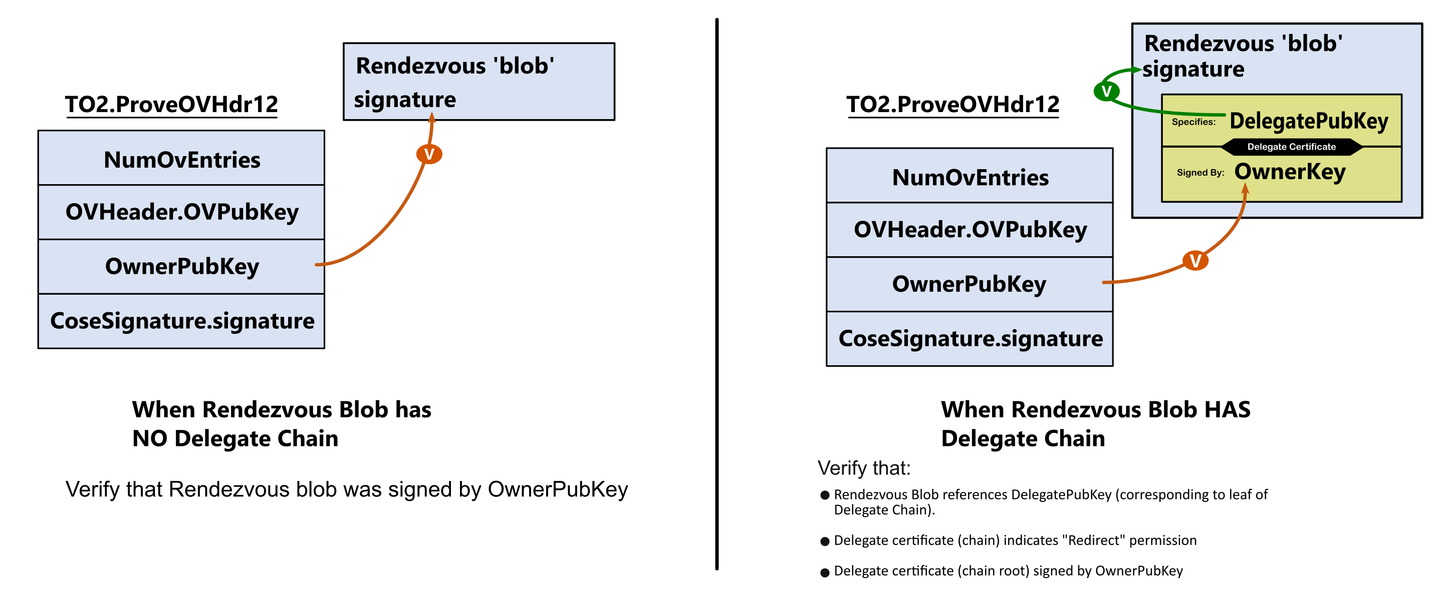
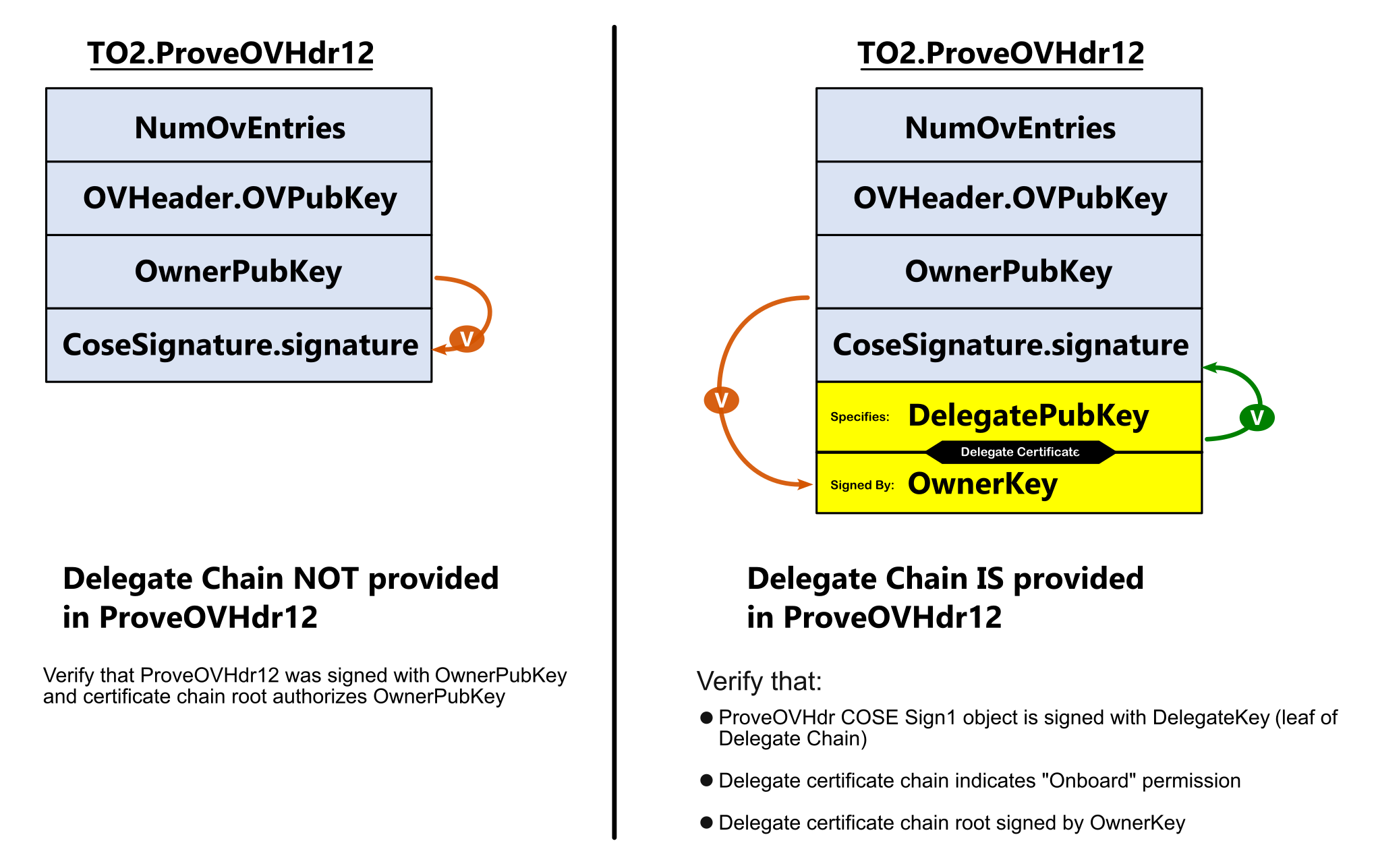
When the Ownership Voucher entries are
transmitted in successive TO2.GetOVNextEntry messages, the Device verifies
the signature chain in the Ownership Voucher, and eventually gets to
the last entry. This entry’s key MUST match OwnerPubKey.
The device MAY compare public keys by comparing key material or using both keys to verify a signature. In a key material comparison, care must be taken to ensure the public key encodings do not cause a false failed comparison. When using keys to verify a signature, the device MAY improve performance by computing the hash of the message once for both signatures, assuming that the cryptographic package makes this feasible.
The following diagram illustrates the process, using only the signature chain, for an Ownership Voucher with 3 entries:
At this point — the contents of the Rendezvous blob and ProveOVHdr20 have proven to have been
signed by the stated OwnerPubKey, either directly, or via Delegation. In the case where Delegation
is being used, the Delegate Chain must express the fdo-ekt-permit-redirect permission - if not, endpoint
MUST terminate TO2 with a DELEGATE_NOT_PERMITTED error.
However, we have not proven the legitimacy of the OwnerPubKey itself. Thus, the final step here is the one
in which we walk the signature chain to prove authenticity of this key, as follows:
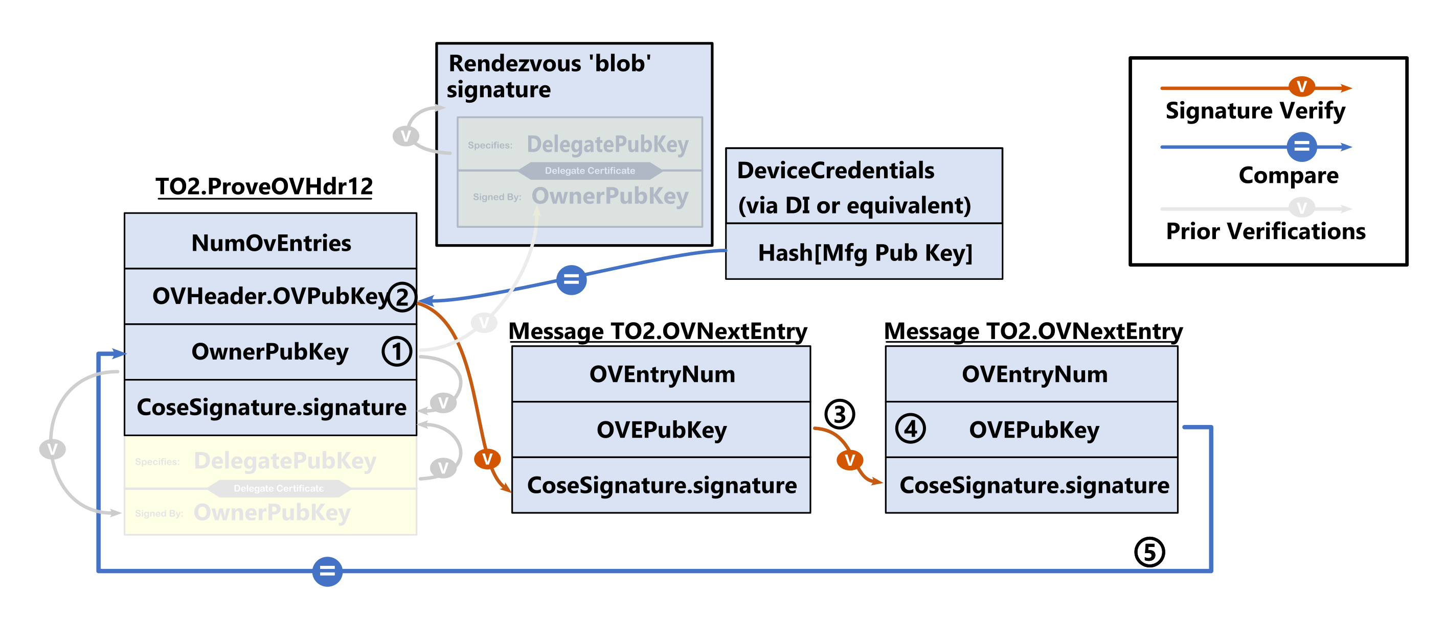
To recap this process, with reference to the diagram:
-
ProveOVHdr20 provides (early access) to OwnerPubKey, for prior verifications of local signature & rendezvous blob
-
ProvOVHdr.OVPubKey is (original manufacturer) base of signature chain (OVPubKey must be verified against hash in device credentails)
-
Each OVEntry signature is verified against the subsequent specified PubKey
-
Last OVEPubKey is deemed to be final and ultimate "Owner"
-
Final Owner (OVEPubKey) verified to match OwnerPubKey
Conclusion: As previous Rendezvous Blob and ProveOVHdr20 signature had been previously matched against now-verified OwnerPubKey — they now proven valid
5.7. After Transfer Ownership Protocol Success
The following are useful steps that SHOULD be performed after TO2 completes, for a Device that is remotely managed after FDO is successful. Since Devices vary, Device owners might have to perform some of these steps earlier or later.
-
The Owner Onboarding Service transfers all device information to the management server.
-
The Device ROE indicates to its OS-level handler to invoke the Management Agent for the Management Service. This Management Agent is then given all the information that the ROE has collected.
-
The Device ROE transitions to the IDLE state.
-
The new Owner changes all credentials in the device, except the Device key (e.g., hardware root of trust) and OCDeviceInfo, and has sufficient information to construct an Ownership Voucher with zero entries.
6. Resale Protocol
After the transfer of ownership completes (i.e., the TO2 Protocol finishes), the
Device switches an internal state variable to inhibit the
device’s software from running FDO, such as is described
for DeviceCredential.DCActive (See § 3.4.1 Device Credential Persisted Type (non-normative)).
A device implementation can also stop a thread or process from running to achieve the same effect, perhaps freeing resources for Device operation. In the case of a MCU-based implementation, the FDO code might only be able to run when external software calls a specific entry point for it.
The Owner can use System or OS level commands to re-enable FDO for a new
transfer of Ownership. How this is accomplished is outside the scope
of this document. In some systems, it can involve setting the
DeviceCredential.DCActive flag to True, but other system-dependent
changes could be needed. In some cases, onboarding with FDO
causes the original FDO code to be removed from storage or
unusable, and another FDO code implementation to be invoked, using
the credentials established in the first run of TO2. For example, a
device might use FDO to download an operating system, then
reboot and run
FDO from within that operating system using the credentials
established after the first run of TO2.
In the TO2 Protocol, the FDO software in the Device ROE stores
new credentials that are only known to the Owner. How the device info
is updated is described in the context of the TO2.SetupDevice20 message
(§ 5.5.11 TO2.SetupDevice20, Type 87)). With reference to this and the Device Credential
(§ 3.4.1 Device Credential Persisted Type (non-normative)), the DeviceCredential.DCPubKeyHash stored in
the device is updated to be the hash of the
TO2SetupDevicePayload.Owner2 key (the Owner2 key is distinct from
the Owner key in the original Ownership Voucher). The change of Owner
key is intended to prevent
this key from being used to correlate the original Ownership Voucher
with the one being generated for resale in the TO2 Protocol.
However, Correlation of Ownership Vouchers using the Device certificate is still possible for some Device attestation key types.
Subsequently, in the [TO2.Done20] message, the Device transfers to the Owner the HMAC of the stored device credentials. This HMAC is used by the Owner exactly as the HMAC supplied to the ODM in the DI.SetHMAC message is used, to create a new Ownership Voucher.
Resale, then, involves the following conceptual steps whose details are device and site dependent, and thus are mostly outside the scope of this document:
-
The current Owner obtains a public key from the target Owner. The Owner retrieves the replacement Ownership Voucher from the latest run of the TO2 protocol, and extends it to the target Owner’s public key.
-
The Device is reconditioned to remove all run-time changes and brought back to a factory state. This includes removing any secrets, except for the FDO credentials from the TO2 Protocol.
-
The Device is set to enable to FDO Device software to run.
-
The Device is powered down, shipped, and re-installed in its new location.
-
The target Owner accepts the Ownership Voucher and enables itself as a FDO Owner. The target Owner implements the TO0 protocol
-
The device onboards to the target Owner. Yet a new Ownership Voucher is created.
It is possible that, when resale time comes, the Owner wishes to change the rendezvous information that is stored in the Device ROE. This can be accomplished by performing a transfer of ownership (using the TO2 Protocol) from the Owner to itself, allowing replacement of the credentials in the TO2.SetupDevice20 message.
6.1. FDO Devices that Do Not Support Resale
A device MAY, at its option, implement only a limited number of FDO transfers of ownership. There are various reasons for this:
-
Each transfer might consume some OTP memory or other system resource, and the total amount is limited.
-
A device is intended to be discarded after its first Ownership Transfer.
-
The ability to use FDO again on a Device might be thought of as an attack vector to disable or even steal control of the device.
-
An Owner could be concerned that the Device’s key will be correlated to its previous onboarded location, giving an attacker more information about the Device.
To prevent FDO from running again, the Owner’s Device Management Service disables all FDO credentials and software after the initial transfer of ownership succeeds.
The Owner MAY indicate to the Device not to permit FDO to operate
again by setting TO2.SetupDevice20...DispositionCode to DispDisable.
A Device MAY also indicate to the Owner that it can no longer perform FDO by setting TO2.DeviceServiceInfoRdy20.ReplacementHMac to CBOR null.
An Owner that does not wish to enable FDO after successful
onboarding can inform the Device by sending:
TO2.SetupDevice20...DispositionCode = DispDisable
Then the Device MUST NOT re-enable FDO for use.
The above directive indicates how FDO is to adjust the state of the Device after a successful onboard, and does not limit the use of the Device afterwards. In any real-world situation, a reinialization of the Device, subsequent to and outside of FDO, can still create an instance of FDO that permits further onboarding. For example, during normal system operation, a new set of FDO credentials can be downloaded and later used.
7. Credential Reuse Protocol
Credential Reuse protocol allows devices to reuse the same Device Credentials across multiple onboardings. Credential reuse is selected by the Owner/Delegate, and accepted or rejected by the Device.
Delegation is a property of the Owner, so credential reuse leaves the Device in a state where the Delegate has not yet been detected. The Device can then be onboarded by the Owner or any valid Delegate of the Owner.
The intended use cases are:
-
To support demos and testing scenarios where the onboarding can be run repeatedly and quickly without having to change the Ownership Voucher or resetting the system after each onboarding
-
To establish a base recovery template with a trusted supplier, so that the trusted supplier could re-establish trust on behalf of the current owner. Where the supplier is always involved in onboarding (e.g., the supplier contractually provides onboarding services to the Owner), credential reuse could be the normal situation. Where the supplier is involved only for system recovery, the Owner/Delegate maintains current credentials, but can revert to the supplier’s credentials in a recovery situation. The supplier and Owner/Delegate MUST ensure a secure result if an attacker resets the Device.
A Device implementation MAY disable credential reuse as a security measure, either directly in the firmware, or using a write-once flag in the hardware.
In addition, a Delegate Certificate must contain fdo-ekt-permit-onboard-reuse-cred
for credentail reuse to be used. An attempt to initate reusue by a delegate
without that credentail SHALL fail with a DELEGATE_NOT_PERMITTED error. (See § 3.5.5 Permissions & X.509 Extended Key Types).
In the resale credential use, the Owner changes the Device Credential in TO2.SetupDevice20, which also creates a new Ownership Voucher. At the end of a successful TO2 protocol, the device deactivates FDO. If the Owner re-enables FDO, the next onboarding uses the new Ownership Voucher.
For credential reuse, the TO2.SetupDevice20 message does not give the Device an update to the Device Credential. The device runs the complete TO2 protocol to the completion, but then remains able to run FDO at the end of the protocol using the same credentials. Since the refresh of credentials is disabled, the Device credentials are known to previous (and potentially future) FDO participants. This can be a security issue, such as if participants are members of different organizations.
The Credential Reuse protocol is enabled if
TO2SetupDevice...disposition = DispCredReuse
In this case, after TO2 is complete:
-
Device does not update the Device Credential,
-
and Device does not internally change the HMAC,
-
and in TO2.DeviceServiceInfoRdy20 message, devices responds with TO2.DeviceServiceInfoRdy20.ReplacementHMac equal to CBOR null.
If the Device does not support the credential reuse protocol, but all other conditions are met, the Device causes a protocol error, and sends an error message CRED_REUSE_ERROR, which terminates the TO2 protocol.
Subsequently, the Device restarts running FDO as for any other failure.
Appendix A: Device Key Provisioning with ECDSA
-
An ECDSA key pair is generated, and a Certificate Signing Request (CSR) is signed with the new private key.
-
The recommended way to do this is to generate the ECDSA key pair and the signed CSR inside the FDO device.
-
If an appropriate security level is possible in device manufacture, it is acceptable for the manufacturer to generate the key pair outside the FDO Device, generate its own CSR, program the FDO Device with the private key, then discard its copy of the ECDSA private key.
-
-
The CSR is submitted to a Certificate Authority trusted by the device manufacturer to create a Device certificate and certificate chain.
-
The device certificate SHOULD NOT expire unless the device manufacturer has a reason for FDO to be performed before a certain date. One such reason is recent discussion about the potential for quantum computers in the future.
-
-
The Device private key is stored with Confidentiality, Availability, and Integrity (CAI) protection in the Device ROE that is performing FDO.
-
The certificate chain is attached to the Ownership Voucher, as described in section § 2.7 The Ownership Voucher.
The Ownership Voucher HMAC, passed in the DI protocol, references the initial Device Certificate. This means that the ECDSA key and certificate must be programmed before the Device Initialize protocol is run. The Manufacturer is trusted to match the Device certificate information to the required DI protocol fields. Subsequent to this, the Ownership Voucher HMAC (OwnershipVoucher.hmac) is used to detect if the Device Certificate is changed in the supply chain.
Appendix B: FDO 2.0 Cryptographic Summary
This section is non-normative
.| Category | FDO usage |
| Device HMAC |
HMAC-SHA256 with HMAC secret (DCHmacSecret) of 128 bits HMAC-SHA384 with HMAC secret (DCHmacSecret) of 512 bits |
| Hash of Owner Key |
SHA256 SHA384 or the device can store complete Owner public key |
| Delegate Certificate | X.509 certificate, can include permissions from section § 3.5.5 Permissions & X.509 Extended Key Types. |
| Ownership Voucher (Owner attestation) |
RSA2048RESTR, RSA2048 or RSA3072
RSA2048RESTR is intended for legacy hardware |
| Ownership Voucher (Owner attestation) | SECP256R1 SECP384R1 |
| Ownership Voucher | SHA256 SHA384 |
| Device attestation ECDSA | secp256r1 (with SHA256 hash) secp384r1 (with SHA384 hash) |
| Key Exchange, DH |
DHKEXid14 (2048-bit modulus) owner and client randoms are 256 bits each
DHKEXid15 (3072 bit modulus) owner and client randoms are 768 bits each |
| Key Exchange, Asymmetric |
RSA2048RESTR RSA-OAEP-MGF-SHA256 Device, Owner Random of 256 bits
RSA2048RESTR, 3072 bits RSA-OAEP-MGF-SHA256 Device, Owner Random of 768 bits SHA256 can be used as mask generation function for RSA-OAEP. However, larger Device and Owner Randoms required for SVK, SEK. Targeted to legacy hardware; use DHKEXid14 or id15 where possible. |
| Key Exchange, ECDH |
secp256r1 or secp384r1, keys used once only, Device, Owner random of 128 bits
secp384r1, keys used once only Device, Owner random of 384 bits Larger Device and Owner Randoms required for SVK, SEK. |
| Key Exchange, ECDH, for legacy devices |
secp256r1, keys used once only. Device, Owner random of 128 bits
secp256r1, keys used once only. Device, Owner random of 512 bits |
| Key Derivation Function |
SHA256 based SEK, SVK entropy is 128 bits (SVK 256 bits, but with lower entropy)
SHA384 based SEK is 256 bits SVK is 512 bits SEVK = SEK || SVK |
| SEK (Session Encryption Key) | 128 bits 256 bits |
| SVK (Session Verification Key) | 256 bits, with 128 bits entropy 512 bits |
| TO2 Session Encryption, AES-GCM | A128GCM, 128 bits A256GCM, 256 bits |
| TO2 Session Encryption, AES-CCM | AES-CCM-16-128-128, 128 bits AES-CCM-16-128-256, 256 bits |
| TO2 Session Encryption, counter mode |
AES-128/CTR IV 16 bytes, Counter is low 4 bytes of IV.
AES-256/CTR IV is 16 bytes, Counter is 4 bytes of IV. Session limits on TO2 protocol prevent counter wrap |
| TO2 Session Encryption, CBC mode |
AES-128/CBC IV is 16 bytes
AES-256/CBC IV is 16 bytes Invalid CBC causes entire connection to fail. this mitigates padding attack |
| TO2 Session HMAC |
HMAC-SHA256 HMAC-SHA384 HMAC-SHA384 state is 512 bits. |
| TO2 Protocol Roundtrip Limit | 1M (1e6) rounds |
Appendix E: IANA Considerations
This section is normative.
Locally Defined Numbers
The following numbers appear in the "Reserved for Private Use"
space of the IANA repository: COSE Header Parameters, and were used in
previous versions of FDO. In this version of FDO, these items are
added to the protocol payload (TO2ProveOVHdrPayload) and these COSE tags are
not used.
CUPHNonce      = 256 ;; iana assignment
CUPHOwnerPubKey= 257 ;; iana assignment
The following numbers are chosen from the "Reserved for Private Use" space of the IANA repository: COSE Algorithms. EPID is not used in this version of FDO.
COSEAES128CBC = -17760703
COSEAES128CTR = -17760704
COSEAES256CBC = -17760705
COSEAES256CTR = -17760706
COSEEPID10    = -2000810  ;; EPID1.0 signature (legacy)
COSEEPID11    = -2000811  ;; EPID1.1 signature (legacy)
The following numbers appear in the the "Reserved for Private Use" space of the IANA repository for CBOR Web Token (CWT):
EAT-NONCE      = 10 ;; iana assignment
EAT-UEID       = 256 ;; iana assignment
EAT-FDO        = -257 ;; iana assignment
EATMAROEPrefix = -258 ;; iana assignment
EUPHNonce      = -259 ;; iana assignment
Appendix F: Changes from FDO version 1.1 to version 2.0
-
A lexicon of key words has been added to the specification.
-
Removed mention of "Delegation Problem" — this term appears in the text of previous versions of FDO as an alternate name for device onboarding. This term is removed here, since Delegation is used as an FDO-specific concept.
-
Capability flags and VendorCap flags are added (§ 3.3.2 CapabilityFlags & VendorCapFlags). Capability flags permit the Device to negotiate supported versions of FDO. It also enables or disables the Delegation mechanism on a per-device or per-Owner basis. A mechanism is provided for older versions of FDO to add a single message to permit backwards compatibility for version negotiation.
-
Delegation added (§ 3.5 Delegation). The main addition to FDO 2.0 is the introduction of the Delegation concept and the use of the Delegate Certificate.
-
Delegation introduces an (optional) enterprise workflow for buying and consuming devices with FDO (See § 3.5.1 Theory of Operation)
-
The delegate certificate (§ 3.5.2 Delegate Mechanism ("Delegation")) is introduced. Signed by the Owner key, it is used by the Owner to authorize delegate sites to onboard on behalf of the Owner.
-
X.509 permissions are added to Delegate Certificates to authorize specific operations (§ 3.5.5 Permissions & X.509 Extended Key Types). Amongst these, Name-Owner Match (NOM) permissions can be used to control which DNS sites are permitted to onboard (§ 3.5.6 Name-Owner Match (NOM) and NOM Constraint Identifiers).
-
-
The order of attestation is changed in the TO2 protocol. Previously, the Ownership Voucher was proved then the Device proved its identity using attestation of the Device Key. We now do this the other way around, with the Device attestation coming first. It is assumed that in FDO it is more common that the Device is new and the Owner (cloud) is established, so the Owner trust in the device takes precedence.
This change causes a reordering of many operations in TO2, making the TO2 protocol be different from earlier versions in essentially every message. Because of this, we renamed every message at least to add a "20" onto the end of the name (this stands for two-point-zero (2.0), not twenty, although protocol developers might find it amusing to read it as twenty).
-
The EPID group encryption mechanism is removed from this version of FDO.
-
Post-Quantum Resilience (PQR) is NOT present in this version of FDO, but crypto suites have been designed to make it easier to grandfather into the spec at a later time. We anticipate updating version 2.0 to add PQR ciphersuites in the future.